.png "Powered by vBulletin")
Originally posted by londonboards
View Post
-
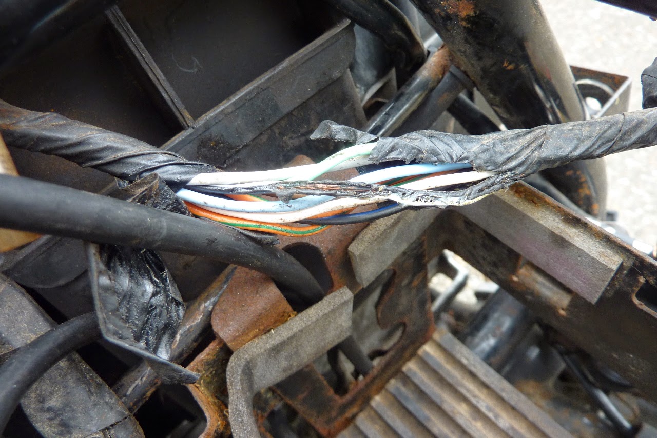
The wire will have got hottest and burntest closest to the short so reducing in heat the further away you go so you might find a place where it isn't burned but best to assume it is and replace the whole piece. -
And here is the wiring that needs fixing. How far up does the damage go?
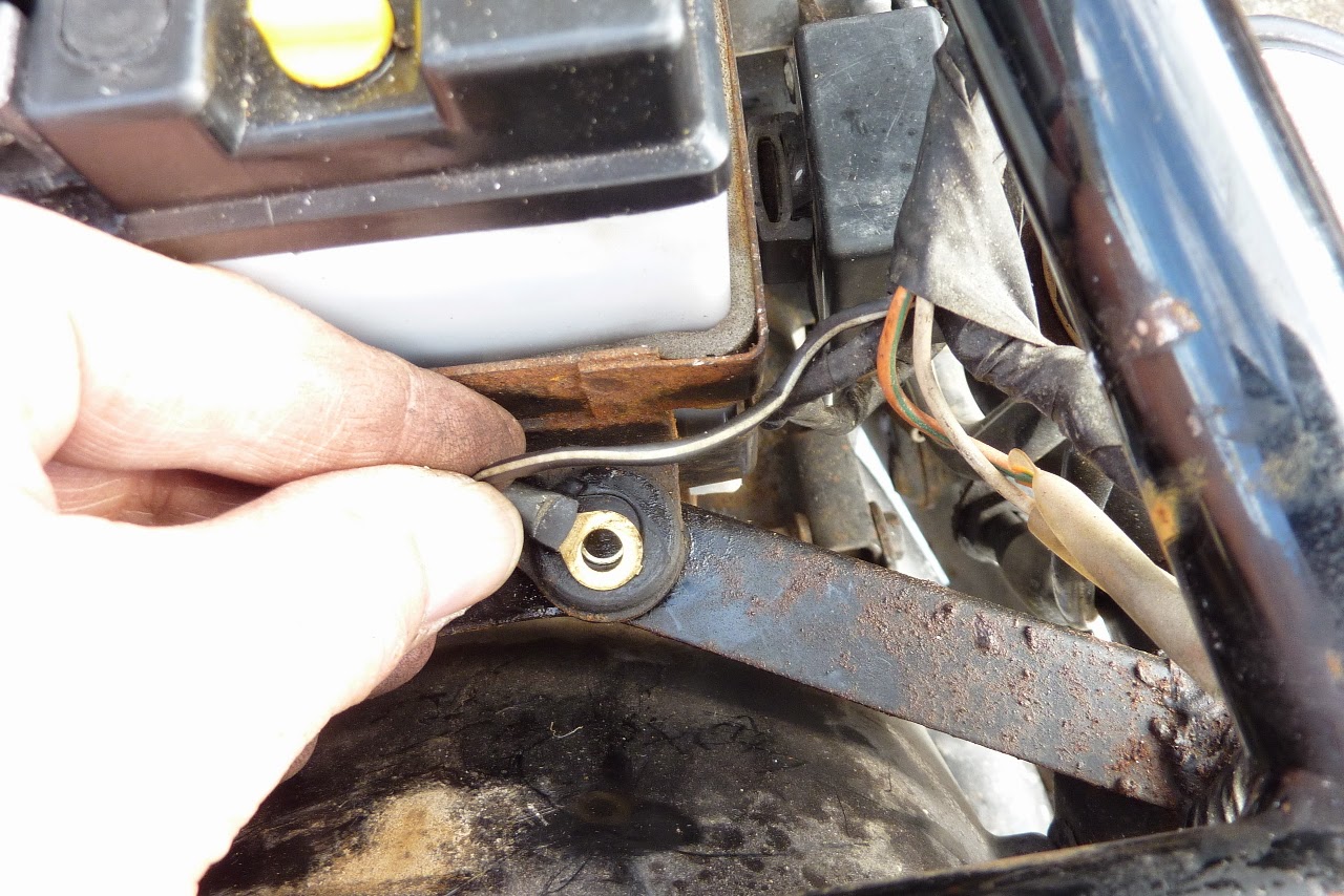


Is this likely to be all the way up to the headlamp shell?
Those wiring diagrams are great but what I need is a wiring loom diagram which shows which cables are bundled together and where they end up.
GreetingsLeave a comment:
-
And here are the results:
My results are:
1). Key off: 12.78v
2). Key on: 12.18v (headlamp on) 12.32v (headlamp off)
3). At idle: 13.2v (at 1,100 rpm)
4). At 2,500 rpm: 13.83v
5). At 4,500 rpm: 14.05v
6). Key Off: 12.90v
These readings are all within prescribed ranges. And I therefore certify the bike as fixed for now.
Except I now have to fix the wiring that was burned up in the process.
Greetings
Leave a comment:
-
New Meter Readings
With the new rectifier installed I got some more meter readings:
GreetingsLeave a comment:
-
 Guest repliedAhhhh, so I guess that was your problem... good luck with the testing
Leave a comment:
-
New Rectifier Installed
Got a new rectifier and tested it out as perfect. Put it on and tidied up some of the wiring including removing the stator headlamp loop and improving the grounding of the rectifier by wiring it directly to the battery (black lead only).
See: My GS Road Runner Blog - New Rectifier

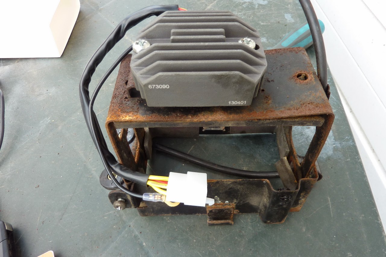
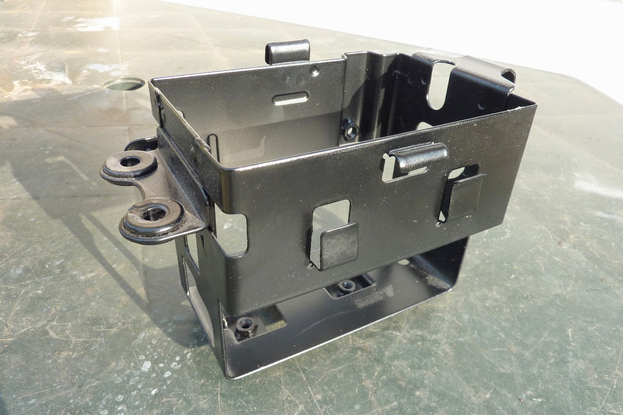
And look, I do know what a nice battery box should look like. Don't have time to refurb this one. I just want to get back on the road. See:
Some of the wiring horror I encountered:
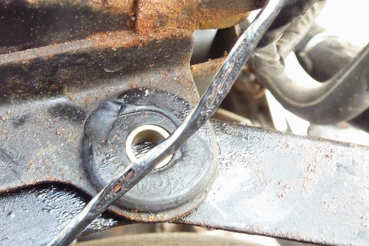
I will be back on the road any day now.
I'm off the Amsterdam in May so it best be ready.
GreetingsLeave a comment:
-
Guest repliedI have a 2nd hand SH-532-12 if you want to try it, (6 wire) msg me on FB just in case I miss it on hereOriginally posted by londonboards View Post
this one .... http://www.ebay.co.uk/itm/suzuki-g10...p2047675.l2557Last edited by Guest; 04-06-2014, 08:19 AM.Leave a comment:
-
tatu -well in so far as a replacement rectifier is required. Probably 2 - one for each bike. Although putting my Dad's rectifier on the GS1150ES shows it to be charging OK. The GS1150 arrived with no rectifier so I still need 2. Think I'll just go with 2nd hand for now.
GreetingsLeave a comment:
-
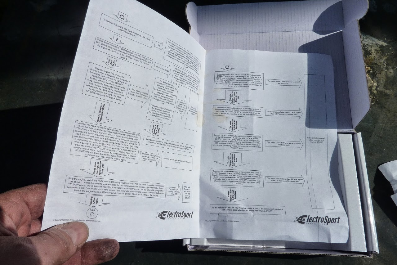
Definitive Regulator Rectifier Testing for Dummies
I have spent a lot of time in the first instance, trying to find out how a multi-meter works and then figuring out how to use it to test my bikes electrics.
Unhelpful (to me) tutorials that state "test for open circuits" or "continuity of the windings close to the approximate resistance values" just make my head hurt. So I set about doing electrics research 101. I wanted to be 100% certain about what I was doing.
YouTube is the best for this if you have the time and patience. I looked at loads of of vids that came up after searching for; motorbike regulator rectifier testing. The result is that I found the definitive video. It's 15 minutes long and is a great tutorial on the job being done by this piece of equipment AND it also describes and shows how to use a multi-meter to perform the tests (if you don't want the theory, skip the first 12 minutes):
A word of caution: this tests will prove a failed rectifier. It will not prove a working one. Nor will it prove that the regulator is regulating correctly. It only tests the diodes on the rectifier. If any of these diodes are not working then the rectifier must be replaced. If they all appear to be working and pass these tests there is a possibility (I am guessing) that the rectifier could still fail under load.
Applying these tests to my Road Runner bike and my Dad's bike's rectifiers, produced the following table of results:

So the rectifier on this bike is toast and the one on my Dad's bike looks bad too.Last edited by londonboards; 04-06-2014, 04:16 AM.Leave a comment:
-
The R/R tests described above must be done with the R/R disconnected from the bike's electrical system. No stator or battery attached. If you try to do it with them attached you will get incorrect readings.
When checking the stator with a Digital Volt Meter (DVM) you need to disconnect the three stator wires from the R/R and measure resistance only, with the engine off. It takes 3 measurements to do verify this. Just randomly mark each of the 3 stator wires as 1,2,3. Them measure between 1 and 2, then between 1 and 3 and finally between 2 and 3. You should read between .5 to 2 ohms between each leg, but nothing higher then 2 or lower then .5 ohms. You should also measure each of the three wires to ground. Those readings should be virtually open. When checking the stator dynamically you measure AC volts with the engine running. Usually a reading between each combinational pair of wires (again 3 measurements) should read above 75V @ 5000K RPMs. This indicates a good stator.
Testing the R/R is a little more difficult. In the case of most shunt style regulators, you're really only testing the diodes but not the regulation capability. The diodes read continuity in one direction and not in the other. Even if you do test the R/R statically using the DVM, you're not guaranteeing that it’s good. Really, the easiest way to test the R/R is to first verify the stator output is good when operating. To do this you simply connect the R/R as normal and verify battery voltage. Assuming that the inline fuse and wiring is good and the battery is in good condition and charged, the battery should indicate a voltage above 14V but below 15.5V at 5000 RPMs it should also read above 13.8V at around 1500 RPMs. If not, then the R/R is bad and move on.Last edited by JTGS850GL; 03-18-2014, 05:22 PM.Leave a comment:
-
eil - that's exactly what I was thinking. I start to do some of these test (as a complete electrical rookie) and nothing makes sense. I tested in on the bike and get one set of readings then I test it off the bike and get another.
I'm glad that I am not going total insane!
GreetingsLeave a comment:
-
13.3V at 3K RPM is actually quite low and possibly indicates that your have poor connections between the Battery and the R/R. With the SSPB that will be taken care of and you will not need to chase it down.Originally posted by londonboards View Post
See the Quick Test in my signature for more details on voltage testing.
There is additional information available by doing this simple test which will help confirm any diagnosis I have done here.
Leave a comment:
-
That test doesn't make any sense. It's saying to put the multimeter in the "diode test function" and then uses volts for expected readings? There are a few problems with this.
The diode test function on most meters is more of a continuity test... if there's "continuity" (typically defined as resistance below an arbitrary threshold) between the two test leads, then beep. Otherwise, be silent. My meter shows the readings in ohms (I believe yours does as well), but assuming that some meters show it in volts, there's the additional wrinkle that different meters use different batteries. Some use a single 9V, some use an array of 1.5V cells. Again... that test, as written, makes no sense.
Furthermore, if this is meant to be a static resistance test, these readings can vary drastically among R/R models because their circuits are not identical. Even if they were, this test would only show you that some of the circuit was behaving properly, it is not a guarantee that all of it is.
My advice would be to test the stator and R/R on the bike per the factory service manual, the procedure for which I summarized in comment #82. I believe posplayr also has some good reference material in his signature which would be worth doing if you want go above and beyond.Leave a comment:


Leave a comment: