• Required reading for all forum users!!!

    Welcome!
    Register to access the full functionality of the GSResources forum. Until you register and activate your account you will not have full forum access, nor will you be able to post or reply to messages.

    A note to new registrants...
    All new forum registrations must be activated via email before you have full access to the forum.

    A Special Note about Email accounts!
    DO NOT SIGN UP USING hotmail, outlook, gmx, sbcglobal, att, bellsouth or email.com. They delete our forum signup emails.

    A note to old forum members...
    I receive numerous requests from people who can no longer log in because their accounts were deleted. As mentioned in the forum FAQ, user accounts are deleted if you haven't logged in for the past 6 months. If you can't log in, then create a new forum account. If you don't get an error message, then check your email account for an activation message. If you get a message stating that the email address is already in use, then your account still exists so follow the instructions in the forum FAQ for resetting your password.

    Have you forgotten your password or have a new email address? Then read the forum FAQ for details on how to reset it.

    Any email requests for "can't log in anymore" problems or "lost my password" problems will be deleted. Read the forum FAQ and follow the instructions there - that's what we have one for...

  • Returning Visitors

    If you are a returning visitor who never received your confirmation email, then odds are your email provider is blockinig emails from our server. The only thing that can be done to get around this is you will have to try creating another forum account using an email address from another domain.

    If you are a returning visitor to the forum and can't log in using your old forum name and password but used to be able to then chances are your account is deleted. Purges of the databases are done regularly. You will have to create a new forum account and you should be all set.

A Voltmeter for Me

  • Thread starter Thread starter Adler
  • Start date Start date
A

Adler

Guest
I've pretty much sold myself on the idea of adding a voltmeter to my bike and I've mostly pieced together how to do it.

Firstly, there is a loose brown wire in my headlight bucket and if I am not mistaken it is both stock and powered when the key is in the on or park position. Seems an ideal place to tap into the electrical system to monitor voltage. Does anyone have any idea why Suzuki put a loose wire in here?

Secondly, the location of the meter. It almost seems like Suzuki wanted me to put something under the idiot lights. Take a look at this picture...

IMAGE_148.jpg


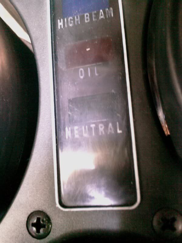
There is a space under the neutral light. The trouble is that it would be awful hard to find a voltmeter with 3 digits that fits into that tiny space.

There are some voltmeters on ebay that are pretty small and cost just about nothing but they aren't THAT small.
http://www.ebay.com/itm/4-5V-30V-Re...159?pt=LH_DefaultDomain_0&hash=item2a13f7cfef

I could also get something fancy like this...
http://cgi.ebay.com/ebaymotors/Out-...r_Truck_Parts_Accessories&hash=item19be1d29f3

But that wont look nearly as pretty as integrating something with my stock gauges.

So thats where im at. Two ideas, neither one satisfy me. Thoughts?
 
Hi,

That wire in the headlight bucket is used for front running lights for those bikes that came with dual filament bulbs up front. It's a nice upgrade available for the rest of us.

Check also JC Whitney, Dennis Kirk, etc, for voltmeters.

Thank you for your indulgence,

BassCliff
 
i have one of those brown hot wires in the bucket of my 83gs1100, and the front turn signals have a dual element buln in them. On my bike i always assumed it was for some kind of option like lights on a fairing .
 
Here's another idea...
I can exchange the center panel of my gauges with one from an 80 550. On my bike the fuel gauge is in the Tach so I could remove the fuel gauge that the 80 had in the center panel and replace it with a voltmeter.

Also, I found this...
http://www.ebay.com/itm/Mini-Red-DC...034?pt=LH_DefaultDomain_0&hash=item2a11d26702

Claims to be 24mm x 21mm x 11mm. I think that will fit. Now ideally I would like a spare gauge cover to modify in case I screw it up so I'll keep my eyes peeled for one.
 
BassCliff - thanks for solving the mystery of my other thread today -- i.e., those orphaned brown wires.
 
Hi,

That wire in the headlight bucket is used for front running lights for those bikes that came with dual filament bulbs up front. It's a nice upgrade available for the rest of us.

Check also JC Whitney, Dennis Kirk, etc, for voltmeters.

Thank you for your indulgence,

BassCliff

BassCliff - thanks for solving the mystery of my other thread today -- i.e., those orphaned brown wires.

Indeed, I had been wondering about those on more than one bike.
 
I have seen some LED voltmeters that change color (green/yellow/red) depending on the voltage. They might fit in the space. It isn't a numeric display but at least warns when things aren't right.
 
Yeah, it's nice knowing you can make it back home! I took a simple solution- $10 Vector meter off amazon, six feet of wiring and voila!

You are out of gas in that picture. Not sure you will actually make it home. :lol:
 
I mounted a digital voltmeter on the dash of my fairing and then put a recently received GS Resources sticker under that. I like the finished product. Now if I could only find a temp gauge and clock that are the same size as the voltmeter to mount on either side.
Unfortunately, the file size of the pic is too large to allow me to post. :(
Willie
 
i have one of those brown hot wires in the bucket of my 83gs1100, and the front turn signals have a dual element buln in them. On my bike i always assumed it was for some kind of option like lights on a fairing .
Even though you apparently don't have a fairing, if your front lights already have dual filaments, there is nothing that says you can't do it to your stock lights. :D


You are out of gas in that picture. Not sure you will actually make it home. :lol:
Look even closer, you will see that he will have to push it anyway.

The engine isn't running, either. :p


Unfortunately, the file size of the pic is too large to allow me to post. :(
Re-sizing a picture is no problem at all. Unless you have a Mac, you have some version of Paint or Paintbrush. Open your picture, use CTRL W and resize by percentage.
I'm sure that Macs have something similar, I just don't know what it is.
shrug2.gif


Another option is to download Irfanview and use its re-sizing options.

However, the option that I have found most useful is PhotoBucket. :eek:
Yep, good ole' PhotoBucket. In my options, I have set it to resize all incoming photos so the long side is 800 and to maintain the aspect ratio.
That way, I keep only my full-detail photo on my computer and it minimizes the storage space necessary on PhotoBucket.

.
 
Here is a new option that appeals to me for a few reasons...

I found this...
vm-2led-circuit.png

http://jhau.maliwi.de/mot/voltmeter.html

Its a pretty detailed schematic for a simple 2-led voltage indicator. If the voltage is too low one LED lights up, too high the other.

This appeals to me because I have always wanted to get into hobby electronics and this is a seemingly easy first project.

I would want to modify the circuit, though, and for that I would need your help.
I think it would be much nicer to have one 2-color LED instead of 2 separate ones and it would also be nice to be able to calibrate the lower and upper voltages. I dont know if thats possible or easy but it would be nice.
 
Oooo. Very nice, its hard not to buy that one immediately. I think I still want to try something home-brewed though.
How do they fit all that into such a tiny package???

Its probably a microprocessor and a few resistors and maybe capacitors, all surface mount components ...

It is under a 10mm led, which is fairly big.

It's probably a very simple circuit, programming the micro is the only kind of hard part ... I breadboarded one that was working (but read a pot vice voltage), but didn't like the way it looked. I might have been able to get it under a 10mm LED.

If I get time I'll figure out how to do your other circuit to be adjustable and use only 1 led (the one with the Red/green LED) You should be able to do it with a single LM339, a diode, 3 resistors and 2 potentiometers.

That would be pretty awesome.
 
Back
Top