N
nater
Guest
Being one of the lucky ones with an electronic tach that no longer works, I wanted to remove it and see if it was as simple a fix as replacing some of the caps, like mentioned here and here. Unfortunately, after replacing everything but the black middle chip, it looks like I'm out of luck.
However, Rustybronco mentioned here about using a LM2917 frequency to voltage converter and redesigning the board, and after some research decided to run with that.
First, I pulled the tach and got it on my bench. You can see the infamous black chip.
Next, I fed the tach a few DC voltages and visually mapped out the deflection of the needle. Since this is done by eye, there is a small amount of error here but could be reduced with more points. You can see the data points I found (and one from one of the original posts) on the graph below:
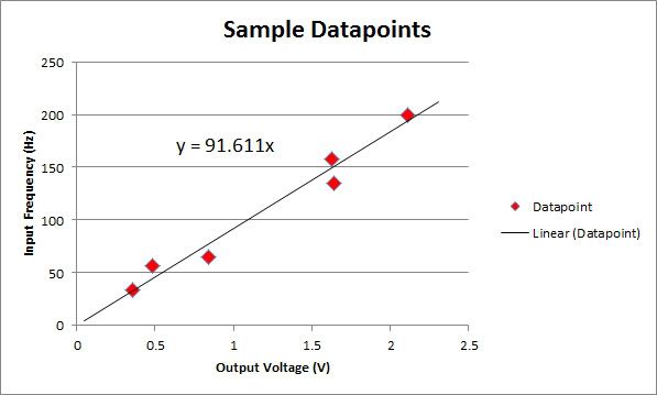
The X-axis is voltage, and the Y-axis RPM / 60. The red dots are each sample point, and the black line is a linear regression model which is included in excel. Then we just take the slope of the line, and use that as the design parameters for the LM2917 circuit:

I've added a zener voltage regulator to the input to protect the circuit and ensure the source is steady, since the output is a function of the input. Finally, wired everything up and gave it a square wave to mimic the signal off the coils...And it works! I took a bunch of sample points off the circuit and plotted them on the original graph:

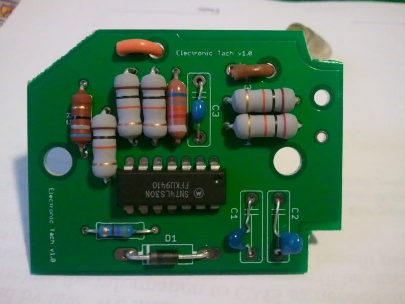
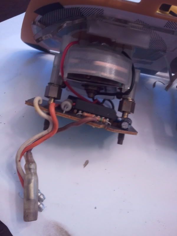
Honestly looks better/more linear than I expected, the response time to a changing input frequency is immediate, and the signal is steady. I've got pics of the circuit but it's just on a breadboard for now. I also hooked it up directly to the tach and it drove the needle without a problem.
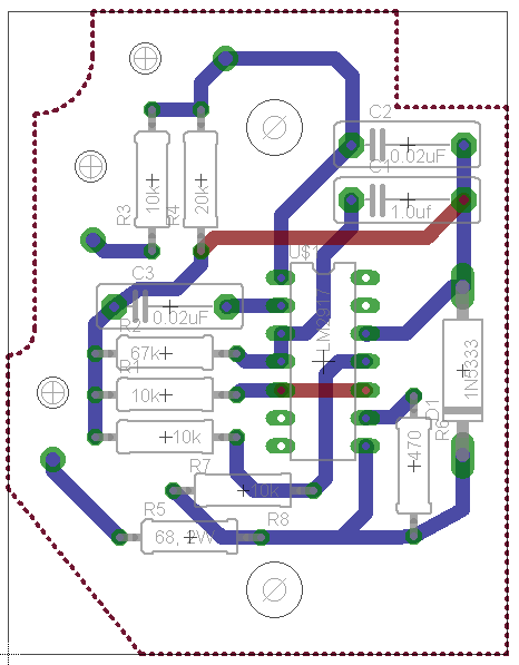
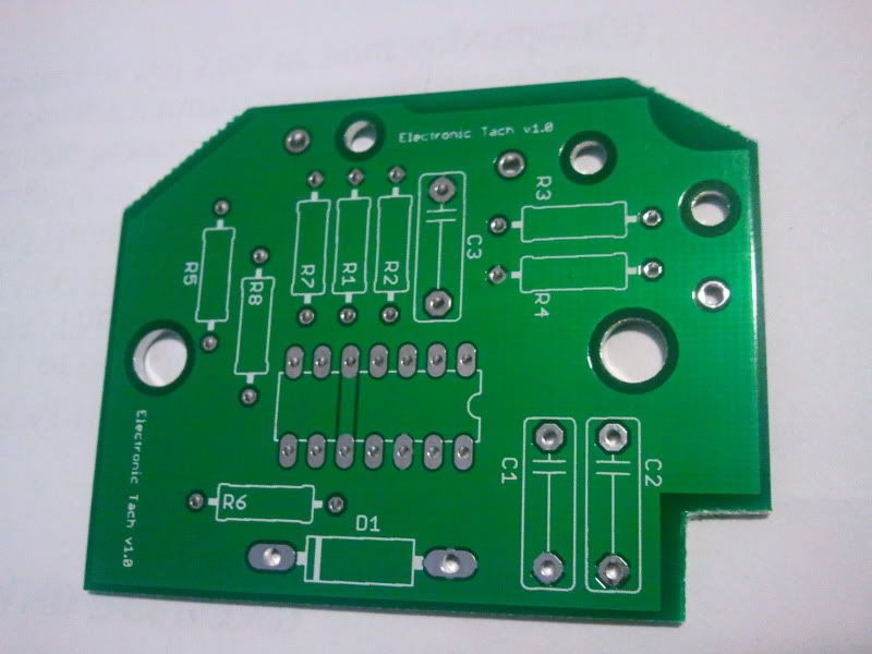
Sparkfun has one-off PCBs, so the next step is getting the design in software and getting a board or two made that it will be a direct swap for the stock board...I'll update as I get there but wanted to show my progress so far
However, Rustybronco mentioned here about using a LM2917 frequency to voltage converter and redesigning the board, and after some research decided to run with that.
First, I pulled the tach and got it on my bench. You can see the infamous black chip.
Next, I fed the tach a few DC voltages and visually mapped out the deflection of the needle. Since this is done by eye, there is a small amount of error here but could be reduced with more points. You can see the data points I found (and one from one of the original posts) on the graph below:
The X-axis is voltage, and the Y-axis RPM / 60. The red dots are each sample point, and the black line is a linear regression model which is included in excel. Then we just take the slope of the line, and use that as the design parameters for the LM2917 circuit:
I've added a zener voltage regulator to the input to protect the circuit and ensure the source is steady, since the output is a function of the input. Finally, wired everything up and gave it a square wave to mimic the signal off the coils...And it works! I took a bunch of sample points off the circuit and plotted them on the original graph:
Honestly looks better/more linear than I expected, the response time to a changing input frequency is immediate, and the signal is steady. I've got pics of the circuit but it's just on a breadboard for now. I also hooked it up directly to the tach and it drove the needle without a problem.
Sparkfun has one-off PCBs, so the next step is getting the design in software and getting a board or two made that it will be a direct swap for the stock board...I'll update as I get there but wanted to show my progress so far

")