• Required reading for all forum users!!!

    Welcome!
    Register to access the full functionality of the GSResources forum. Until you register and activate your account you will not have full forum access, nor will you be able to post or reply to messages.

    A note to new registrants...
    All new forum registrations must be activated via email before you have full access to the forum.

    A Special Note about Email accounts!
    DO NOT SIGN UP USING hotmail, outlook, gmx, sbcglobal, att, bellsouth or email.com. They delete our forum signup emails.

    A note to old forum members...
    I receive numerous requests from people who can no longer log in because their accounts were deleted. As mentioned in the forum FAQ, user accounts are deleted if you haven't logged in for the past 6 months. If you can't log in, then create a new forum account. If you don't get an error message, then check your email account for an activation message. If you get a message stating that the email address is already in use, then your account still exists so follow the instructions in the forum FAQ for resetting your password.

    Have you forgotten your password or have a new email address? Then read the forum FAQ for details on how to reset it.

    Any email requests for "can't log in anymore" problems or "lost my password" problems will be deleted. Read the forum FAQ and follow the instructions there - that's what we have one for...

  • Returning Visitors

    If you are a returning visitor who never received your confirmation email, then odds are your email provider is blockinig emails from our server. The only thing that can be done to get around this is you will have to try creating another forum account using an email address from another domain.

    If you are a returning visitor to the forum and can't log in using your old forum name and password but used to be able to then chances are your account is deleted. Purges of the databases are done regularly. You will have to create a new forum account and you should be all set.

Figured why gs750 not starting

  • Thread starter Thread starter baz666
  • Start date Start date
Check out http://auto.howstuffworks.com/motorcycle1.htm

Midle of the first page there is a little animation that shows how the cam/valves/pistons/crank work in relation to one another.

It explanes why you need to have the crank and cams in the correct possition better than i can.

After looking at the animation, imagine if your cam was off a tooth. You would be opening or closing the valves too early or too late. Off a couple teeth and you are going to be contacting valves to pistons and bending/breaking things.
 
Last edited:
You don't have to completely remove the cams, but you will need to remove the caps for both cams. Lift the intake cam out and rest it between the intake and exhaust valleys. Lift the exhaust cam up, orient the #2 in between two links (pulling up on the chain in front of the cam) and then install it. The intake I would locate link 10 and link 11, place the arrow between them, and slowly work the cam back into its location in the head.
Hope that helps a bit.
 
I think I'm not understanding something.
If the crank and the two cams are already in the positions they should be, with the T mark lined up and the the 2 and 3 arrows facing straight up, as in the photo I took, what difference does it make where the cam chain is?
Isn't the point to have the crank and the two cams properly positioned or does the chain position also have an effect. Maybe I'm not realizing whether it works in some other way rather than just connecting the crank to the cams. Any clearing of the fog would be greatly appreciated.
thanks,
baz
 
One thing I forgot to mention that is very weird. In the manual it says to measure the cam chain's 20 links and the total should come out to 157.8mm or 6.21 inches. The manual does say to do this while pulling the chain taut when it's out of the engine.
With the cam chain still in the engine I measured the 20 links and they came out to 148.1mm. I measured with a vernier gauge and then with a steel ruler and still the same number. How is that even possible? Unless the 750E engine is a lot different than the 750ES.
 
I think I'm not understanding something.
If the crank and the two cams are already in the positions they should be, with the T mark lined up and the the 2 and 3 arrows facing straight up, as in the photo I took, what difference does it make where the cam chain is?
Isn't the point to have the crank and the two cams properly positioned or does the chain position also have an effect. Maybe I'm not realizing whether it works in some other way rather than just connecting the crank to the cams. Any clearing of the fog would be greatly appreciated.
thanks,
baz


Basically the spacing on your chain is not quite right (off a tooth).

IT's got to be evenly spaced over the exhaust and intake sprockets to allow the chain to roll smoothly and don't bind and to ensure the cams spin at the right times.

If you are off a tooth it can cause causing rough running (if lucky) or damage an wear as the valves open/close at the wrong times.

If you were to spin the crank a couple times with the timing chain miss aligned (don't do it!), the cams would probably not come back to the same orientation as you had initially set them (even though they look correct right now), and you might get some binding and or contact with pistons/valves.

Proper alignment of the cam chain and evenly spacing it will effect compression
 
Okay, that makes sense. I'll do as instructed, following the rebuild instructions in the manual.
Sorry about all the obvious questions, I'm a little overwhelmed by this, aside from not having the sharpest mechanical mind - but I've gotta say, I am learning A TON!
thanks to everyone who's taken the time,
baz
 
One thing I forgot to mention that is very weird. In the manual it says to measure the cam chain's 20 links and the total should come out to 157.8mm or 6.21 inches. The manual does say to do this while pulling the chain taut when it's out of the engine.
With the cam chain still in the engine I measured the 20 links and they came out to 148.1mm. I measured with a vernier gauge and then with a steel ruler and still the same number. How is that even possible? Unless the 750E engine is a lot different than the 750ES.


Review the picture in your manual.

It shows the measurement to be 21 PINS.

Start on the second roller pin on a link, then count off 9 full links, and set the rule to the second roller pin of the 10th link.

(picture says it much better than I can)

Nic
 
Okay, that makes sense. I'll do as instructed, following the rebuild instructions in the manual.
Sorry about all the obvious questions, I'm a little overwhelmed by this, aside from not having the sharpest mechanical mind - but I've gotta say, I am learning A TON!
thanks to everyone who's taken the time,
baz


You will know that bike backwards and forwards by the time you are done.

Keep asking questions, and get your hands dirty. Sometimes learing by doing is the best way.

It may seem intimidating now, but it will all fall into place the more you work on it. :D
 
Review the picture in your manual.

It shows the measurement to be 21 PINS.

Start on the second roller pin on a link, then count off 9 full links, and set the rule to the second roller pin of the 10th link.

(picture says it much better than I can)

Nic

Ah.... said the blind man... :o
thanks once again from the Doh! Dept.
 
I am glad the guys caught that as it looked right to me but I've got a cataract in one eye and things sometimes get fuzzy.

They are right of course, if it is off by one pin it could be disaster so take your time and check and then double check.

You've come a long way in a short time and your doing a good job just take your time. I find rushing things is when we make mistakes that could be costly.

She be running sweet in no time.

cheers,
Spyug
 
WRT (with respect to) the number of links being important:
Setting the marks on the cam sprockets correctly will time the cams to the crank. Getting the link count correct times the cams to each other. You don't want one cam to still be closing a valve when the other cam is opening the same cylinder's valve. They could possibly hit each other and all hades would break loose. Best case scenario would be popping, backfiring and/or loss of power.
 
Thanks for the encouragement, Spyug.
There's one other thing I'm wondering about:
I noticed in the manual there are references to TDC and BTDC and the necessary degrees cams and crank must be positioned when valves are opening and closing.
I noticed in Nic's photos of his rebuild he used an APE degree wheel when setting up the cams. Is this something I should be doing and if so, how does the degree wheel work?
thanks for all,
baz
 
TDC = top dead center
BTDC = before TDC

No, you don't need to use a degree wheel to set your cams correctly. Small (1-5 degree) changes in cam timing (achieved by slotting the cam gear holes) will yield more torque or more horsepower depending on where you set the cams. That's why you use a degree wheel

That's an advanced tuning method.

Get your bike running first and don't worry about degreeing your cams

yup.


I'm actually using non stock cams in my bike now, so to optimize them, I had to degree them in.

Use the stock settings for now, get it running, then down the road if you pick up some hotter cams and want to experiment, get some slotted gears and degree them in.

Nic
 
Check out http://auto.howstuffworks.com/motorcycle1.htm

Midle of the first page there is a little animation that shows how the cam/valves/pistons/crank work in relation to one another.

It explanes why you need to have the crank and cams in the correct possition better than i can.

After looking at the animation, imagine if your cam was off a tooth. You would be opening or closing the valves too early or too late. Off a couple teeth and you are going to be contacting valves to pistons and bending/breaking things.

:confused: 
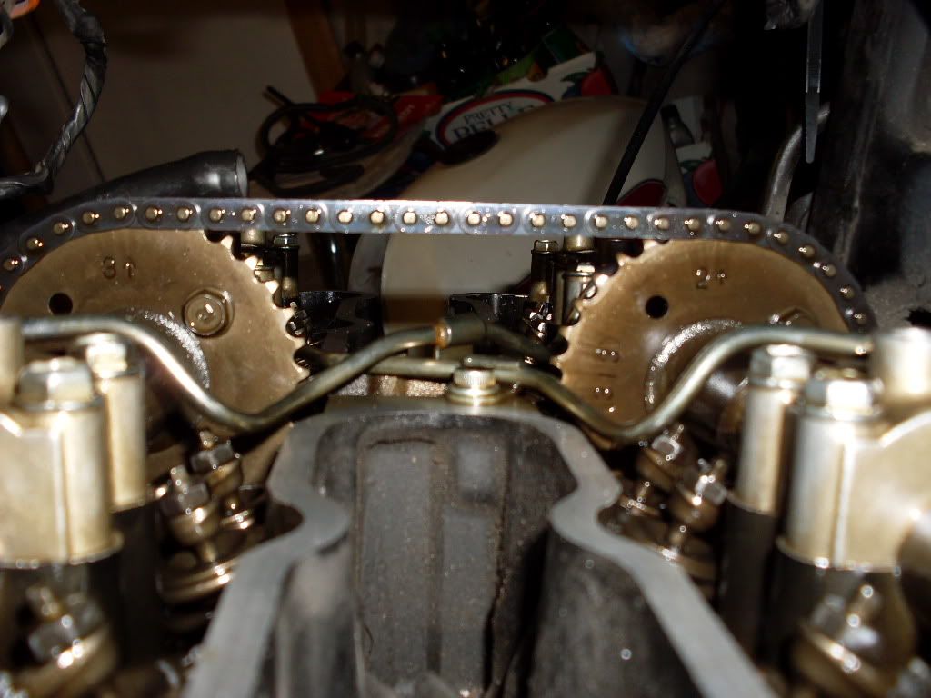
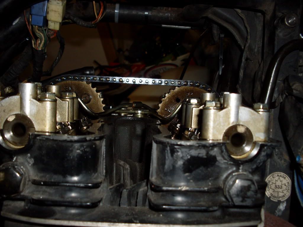
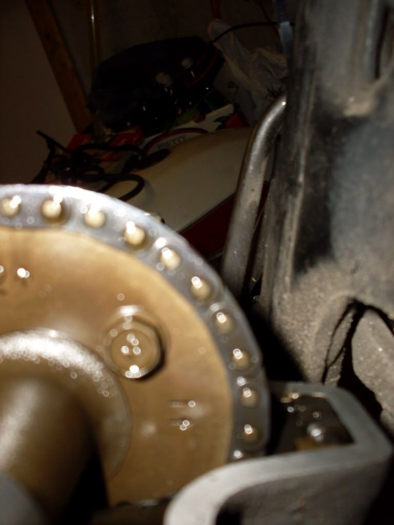
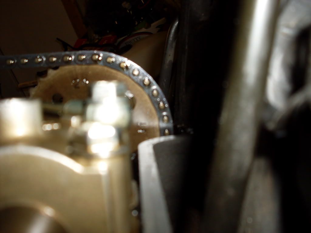
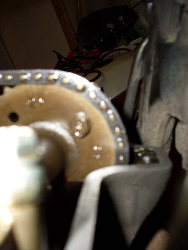
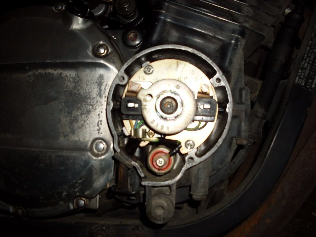
The strange thing is, the cams are not off their mark in relation to the crank. With the crank's T mark lined up with the 1-4 mark on the signal generator, the intake cam's 3 is pointing straight up and so is the exhaust cam's 2 and the exhaust cam's 1 is pointing straight forward, right where they're all supposed to be. (see photos below) The lines and notches on the ends of the camshafts themselves are also lined up with the cyl head gasket surface, as required in the manual. The only thing is that the cam chain itself is in the wrong position with the sprockets on both cams engaged between full links - ie: with one sprocket tooth in one link and the next sprocket tooth in the next link. Very weird. It makes me wonder not only how it happened but what the difference is between the current positioning and if I turn the cams so that the sprocket teeth engage in full links. The cams and crank will still be in their current correct position. Or am I missing something here?
Also, I'm trying to visualize how I would actually move the cam chain so the sprockets on each cam are sitting in full links. It's like I would have to somehow disengage the cam chain from the crank and move it forward half a link, then engage the two camshafts so the two teeth in each camshaft are engaged in full links.
It's seems like the cam chain itself jumped half a link.
If I disengage the camshafts and move the crank half a link then re-engage the camshafts, the crank will then be out of position since it's T mark is currently lined up with the 1-4 on the signal generator.
I know I'm being a pain the butt here but as I said, I'm having a hard time understanding what's going on here.

SDC10293.jpg

SDC10292.jpg
 
Last edited:
If what I am seeing in the pictures is correct and the 1-4 T on the crank is in the correct spot your setup is spot on. It has been 20 years since I've had one apart ( 81 1100E ) so I pulled out my old 1100 manual and my new 750 manual and they both agree you did it right. The number of pins is 20 and pin 1 is the pin over the 2 on the EX cam, the 20 pin is the one directly over the 3 on the IN cam.
 
Last edited:
Anybody have any clue what the next step should be if the two cams and crank already line up AND the cam chain teeth do not sit in full links?
thanks,
baz
 
Below are photos of the cam chain position and the crank mark position, which are all where they are supposed to be, according to the service manual.
The only thing is - as I've mentioned before- is that cam chain sprockets have one tooth in one link and the next tooth in the following link.
A couple of the photos a are a little blurry due to my fumble fingered camera use but I think you should be able to see the relative positions of the cam sprockets and crank.
thanks for all the help,
baz
SDC10304.jpg

SDC10302.jpg

SDC10310.jpg

SDC10299.jpg

SDC10293.jpg
 
If anybody can give me their ideas on the photos below, I'd be most obliged.
thanks,
baz
 
Back
Top