G
Guest
Guest
I'm trying to find a tool to hold the rotor. So far I've only been able to get it up to 65-lbs. Using a strap wrench.
Required reading for all forum users!!!
Welcome!
Register to access the full functionality of the GSResources forum. Until you register and activate your account you will not have full forum access, nor will you be able to post or reply to messages.
A note to new registrants...
All new forum registrations must be activated via email before you have full access to the forum.
A Special Note about Email accounts!
DO NOT SIGN UP USING hotmail, outlook, gmx, sbcglobal, att, bellsouth or email.com. They delete our forum signup emails.
A note to old forum members...
I receive numerous requests from people who can no longer log in because their accounts were deleted. As mentioned in the forum FAQ, user accounts are deleted if you haven't logged in for the past 6 months. If you can't log in, then create a new forum account. If you don't get an error message, then check your email account for an activation message. If you get a message stating that the email address is already in use, then your account still exists so follow the instructions in the forum FAQ for resetting your password.
Have you forgotten your password or have a new email address? Then read the forum FAQ for details on how to reset it.
Any email requests for "can't log in anymore" problems or "lost my password" problems will be deleted. Read the forum FAQ and follow the instructions there - that's what we have one for...
If you are a returning visitor who never received your confirmation email, then odds are your email provider is blockinig emails from our server. The only thing that can be done to get around this is you will have to try creating another forum account using an email address from another domain.
If you are a returning visitor to the forum and can't log in using your old forum name and password but used to be able to then chances are your account is deleted. Purges of the databases are done regularly. You will have to create a new forum account and you should be all set.
I'm trying to find a tool to hold the rotor. So far I've only been able to get it up to 65-lbs. Using a strap wrench.
I put mine in 2nd gear and held the rear brake.Just go slow and sneak up on that 90lbs.Be sure the crank snout and inside of the rotor are completely clean and free of oil residue.


So I've made a few videos with the Dynojet kit.
With and without restrictors
With and without 1 restrictor
Stock VS no restrictors
So Pete, It looks like either reducing the springs or enlarging the slide hole will cause the slide to open quicker.

Looks good. Thanks.
How do you degree your valves on this head?
I'm having a hard time getting my dial needle down to the bucket without hitting the cam. We are installing the cams straight up.I will degree the cams after break in and do some additional tuning.I am looking into how other motorcycle engines have their cams degreed properly.I've never done it on a motorcycle.I have on auto engines,so that will help.
Where can you get the cam's and what kind of numbers are you using ? From my understanding,the stock cams were sent to Megacycle along with the intended use and they calculated the proper lift and duration.The cams were welded up and ground back down to spec.Dgyver can't find the spec sheet.
I've noticed that my timing chain is stretched a bit and the timing is out. I think its sitting at around 110 + right now. Our chain is original to the engine and doesn't appear to have much wear at all.I had to really look to find polished spots from the cam gear teeth.I will check ours but I believe we will be fine on that.I am using an adjustable manual cam chain tensioner.If your cam chain is stretched,it may be time for a new one.Cheap insurance for a built engine.
I just finished a set of cam sprockets and a new degree wheel for it so now I have something more accurate to play with.That sounds good.
Those videos are very intriguing... but they do definitely confirm what I feel...
Reducing the springs *and* enlarging the vacuum hole = awesome
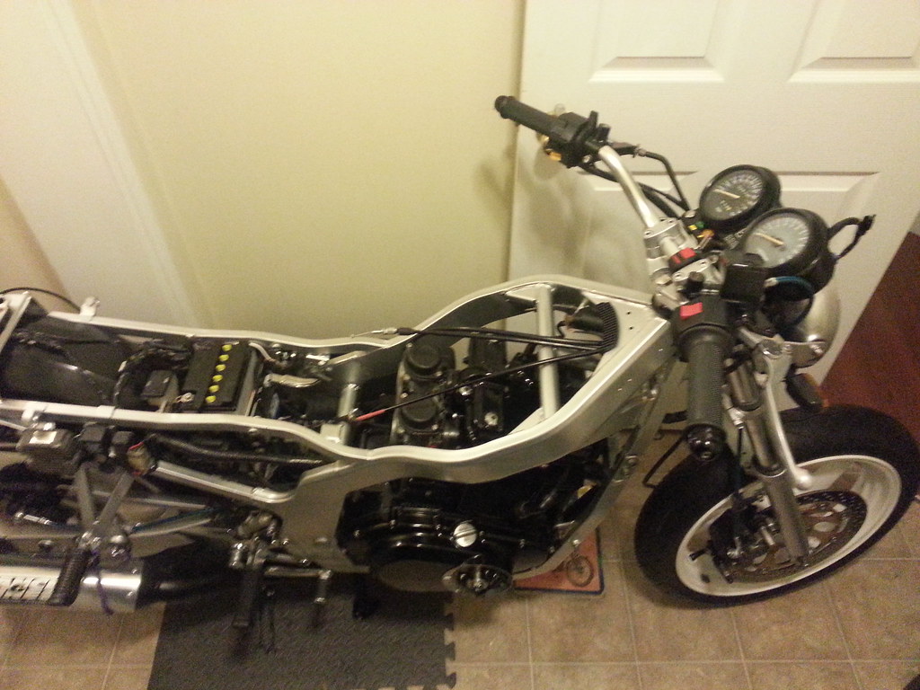
Ben, looks like she's gonna be a beast!
 . Once I set it to stock and confirmed with a dial indicator, everything lined up perfectly.
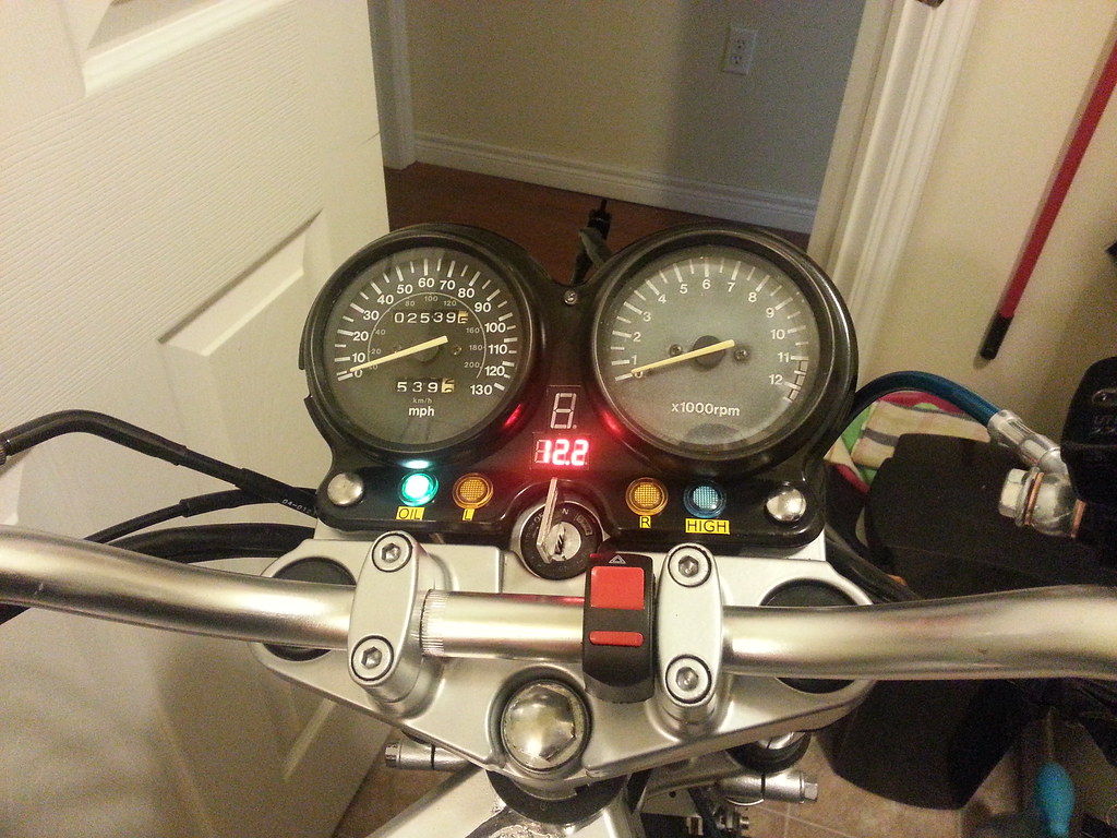
Turns out that my timing is fineand the chain is only 0.009" stretched. It was my tdc reference that was off. The ignitor rotor pin hole on the crank was drilled. That allows for a 10 degree advance
But I still have not been able to check the numbers yet because I can't get my dial needle in a good spot to measure.
I've done it plenty of times on my other head.
I've never seen an advance done like that.I have a Bob B. 5* advanced rotor.He has a jig that allows him to weld up the factory hole and redrill it with a 5* advance.Works a treat on my bike.
I am not sure where a good place would be to set up a dial indicator.I had a base and holder that I made for AMC Jeep engines that bolted down to the valve cover bolt hole.Of course it worked on other engines as well.

")


The PCV valve is being used as a one way valve allowing a negative pressure to form in the case and not letting pressure build up.
It shouldn't be any more of a restriction than the original airbox was.
") SO I'm left with cleaning it out with more acetone. I don't think I'll need to seal it because I can see nice metal material under it. I've tried to desolve the gunk in gas and it won't do a thing to it.
SO I'm left with cleaning it out with more acetone. I don't think I'll need to seal it because I can see nice metal material under it. I've tried to desolve the gunk in gas and it won't do a thing to it.