• Required reading for all forum users!!!

    Welcome!
    Register to access the full functionality of the GSResources forum. Until you register and activate your account you will not have full forum access, nor will you be able to post or reply to messages.

    A note to new registrants...
    All new forum registrations must be activated via email before you have full access to the forum.

    A Special Note about Email accounts!
    DO NOT SIGN UP USING hotmail, outlook, gmx, sbcglobal, att, bellsouth or email.com. They delete our forum signup emails.

    A note to old forum members...
    I receive numerous requests from people who can no longer log in because their accounts were deleted. As mentioned in the forum FAQ, user accounts are deleted if you haven't logged in for the past 6 months. If you can't log in, then create a new forum account. If you don't get an error message, then check your email account for an activation message. If you get a message stating that the email address is already in use, then your account still exists so follow the instructions in the forum FAQ for resetting your password.

    Have you forgotten your password or have a new email address? Then read the forum FAQ for details on how to reset it.

    Any email requests for "can't log in anymore" problems or "lost my password" problems will be deleted. Read the forum FAQ and follow the instructions there - that's what we have one for...

  • Returning Visitors

    If you are a returning visitor who never received your confirmation email, then odds are your email provider is blockinig emails from our server. The only thing that can be done to get around this is you will have to try creating another forum account using an email address from another domain.

    If you are a returning visitor to the forum and can't log in using your old forum name and password but used to be able to then chances are your account is deleted. Purges of the databases are done regularly. You will have to create a new forum account and you should be all set.

Ignition switch connector??

  • Thread starter Thread starter Guest
  • Start date Start date
G

Guest

Guest
Okay, so while replacing my front brake lines last week I decided to clean up the triple tree area while I had access.
Upon wiping down the black nylon bag behind the gauge cluster I heard stuff fall out & hit the floor.
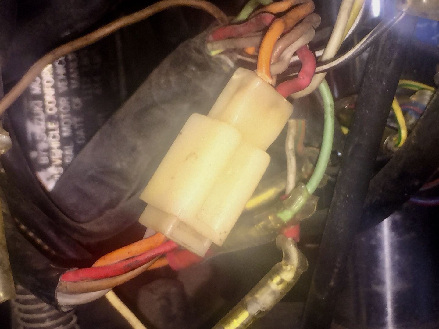
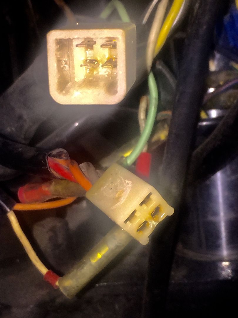
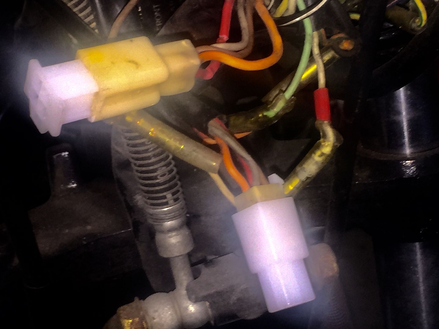
Pieces of a connector- great! Further investigation discovered this(see attached photo).
If my research is accurate I'm looking at the ignition switch connector. The wire colors and count are my only tip-offs.
Searching within vintageconnections.com I locate these:

http://www.vintageconnections.com/Products/Detail/67

My questions for the most all knowing are: Is this truly the ignition switch connector I believe it to be?
And, Are those connectors above from vintageconnections.com the direct 'plug-n-play' replacements for the ignition switch (or whatever this connector is for)? Mind you the harness looks great overall, so the terminals are A-OK...they just need a 'stable stable' ;)
Thanks in advance.
 

Attachments

  • BadConnector_02.jpg
    BadConnector_02.jpg
    100.7 KB · Views: 0
Last edited:
Yes,
the red, orange, brown, gray harness/connector is for the ignition switch.

Red from main fuse
Orange goes back to the fuse block to power the Head, Signal & Ignition fuses.
Other two are for the tail light (and tail light only) circuit, in ON position the two are connected so powers the tail light with same circuit as the other signals. In Park position the red (main ) is connected to the brown tail light wire, so the tail light (and tail light only) is powered by the main fuse.
But that is not what you are asking.
 
Last edited:
Confirmed, that is the connector for the ignition switch.

Confirmed, yes, the connector from Vintage Connectors will work just fine.

Not sure if the actual brass terminals will work in the VC housings, but they probably will.

If you need confirmation of that, I can find out in the morning.

.
 
Thanks again, guys! Order goes in today. I'll not trouble you any further, Steve...but if curiosity gets the best of you....lol.
All the best :)
 
Last edited:
Have a look at the handlebar switch plugs under the tank as well. If the ign has gone brittle, they may not be far behind.
 
Judging from the picture the contacts in the connector got oxidized/corroded which caused excessive heating, which in turn causing the plastic connector housing to become brittle.
 
Not sure if the actual brass terminals will work in the VC housings, but they probably will.

I'll not trouble you any further, Steve...but if curiosity gets the best of you....lol.
OK, I looked at the '80 850G parts bike, here is what I saw:

45BC98C8-0A12-4DAE-B546-7A34D023391C_zpsbs6dtmi1.jpg


It took a bit to separate the connector halves:

D60D228E-4C08-4C7B-93DC-5A9AC6BA5609_zpsat0jpxm1.jpg


The release pins in the brass tabs did not want to co-operate by actually releasing, but I was at least able to verify that the connector shells from Vintage Connections DO mate properly with the OEM connectors:

83E09208-F6E5-4025-A7AF-260E5FAAAC1F_zpsdirjngtl.jpg


I would suspect that if you could get the brass pieces out, they would likely snap into the new housings, but based on the condition of the wire just outside the connector, you would probably be better off just snipping them off and installing new ones. :encouragement:

.
 
OK, I looked at the '80 850G parts bike, here is what I saw:


D60D228E-4C08-4C7B-93DC-5A9AC6BA5609_zpsat0jpxm1.jpg


.

The female (pin side)shell shows clear signs of heat melting the plastic. The male (pin) side looks like it has some type of dielectric grease; hopefully that has stabilized the situation. I guess it is aparts bike, but it is still good for members to be able to diagnose what they are looking at.
 
It's also somewhat important to know that ALL of the current required to run EVERYTHING on the bike goes through two of those rather small pins. The red wire comes from the battery (until the R/R takes over), the orange wire carries the current from the ignition switch to the fuse block. ANY corrosion or dirt in those two sets of pins will heat things up quite nicely. You can see the slightly-melted plastic in that last picture that you showed.

.
 
Wow! You've gone all out, Steve - Thanks once again! Yeah, I saw that corrosion around the end of the crimped areas. I'll go thru it more thoroughly once the VC parts come in. With extra pins there's no reason to not use them where it's this critical. I wasn't completely aware of how much current this connector sees, so I've learned not to compromise here. I'll post how it all goes in the next few weeks.

Thanks for everything, Gang - You all rock!
 
Well, Vintage Connections delivered so quickly I was able to get the connector replaced this morning. The wires & terminals were cleaned up with De-oxit beforehand & proved that the terminals were solid (see attached photo).
BadConnector_13.jpgDielectric grease added to the connector cavities, and then I wanted to wrap it in fusion tape but I guess the dieletric wouldn't let the tape cling to itself, so ditched that idea. Fit & finish are spot on for this ignition connector-exact replacement.

NOTE: This is the 'non-latching' variety whereas I think Steve tried fitting a 'latching' type earlier, which probably works as well, just not as factory originally installed. Apparently, VC had a minimum $$ order policy, so I had to buy 4 connectors to meet that...still under $20 & a wise investment (how long will these be available from now??). Better than new! I'm very happy with this quick & easy fix...but then....
 
What Holy Matrimony is THIS?

What Holy Matrimony is THIS?

While trying to get a good photo view of the completed task, I discovered THIS head-scratcher:OpenOrangeWire_01.jpg


From what I can muster this orange wire is coming in from the fuse/relay panel via the primary frame harness. If that's the case, how are all my lighting/accessories functional with this orange wire dangling in the breeze?!? I can't find a point of connect & it can't be something I broke while
futzing around the ignition switch contacts. I feel this was deliberate during the Vetter fairing install (yeah, the bike has a Windjammer IV w/radio).


Three different wiring schematics studied & at best I assume it was an added tap from factory for future accessories...at least ONE schematic has me leaning in this direction. Battery is off location under tender, so can't test if live, switched, etc. Please enlighten me. Thanks yet again, Guys.
 
What I have done on a fresh/new harness is:
1. Slip an oversized price is shrink tubing over one end of the connector.
2. Snap the connectors together and Use a small zip tie around end(through the wire ends).
3. Use heat gun to shrink the tubing.

This is not water proof and
of course this is semi permanent but it keeps the connectors looking fresh.
Along with dielectric grease offers good protection.
 
That's a good idea! I began thinking that any covering would build up heat from current draw, so left it exposed to breathe.

Now, about that orange wire...any guesses? I'd like to put this behind me & take on the next task. TIA :)
 
That orange wire at the front of your picture appears to disappear into the Vetter harness, not the bike harness. (I see a purple wire going into the same harness and Suzuki did not use purple wire.) The Vetter wiring diagram shows an orange wire feeding the optional horns, so I would guess that if you open your left fairing pocket, you will find an orange wire there, too, and it will also be disconnected.

attachment.php


.
 
Well this holds the most logic thus far, Steve-Thank You Thank You! I'll confirm this tomorrow after work, but you're most likely right. Now if I was to tell you I found a schematic off of Basscliff's site that has a 'P' wire not listed in the color key you'd probably not believe me. But this schematic also has an orange wire feeding a lot of accessories I simply don't have (fuel gauge, side stand warning light, oil temp, etc). I began thinking this wire had no purpose on my model year, so it got nicked...literally. To not mask it off is rather shoddy practice, thou...just sayin'.
 
You nailed it, Steve-Vetter harness wiring! You're a GOD!!

Thanks for the tip, BigT. I'm kinda on the 'If it ain't broke' fence right now, so I'll not tear into the switch just yet. The connector replacement came to me as an unknown discovery, not an electrical failure being chased down (everything functioned normally beforehand). What I might do thou is find an as-is ignition switch I can disect so as I can see what I'll be up against-I AM curious to know. That'll build my confidence in cleaning up the bike's original switch in the future :)

Thanks again, All.
 
There's two bolts holding the switch on and one screw holding it together

You've got some heat buildup going on and it's not going to get better
 
On the other hand...access to the switch is pretty convienent atm...no springs or other pieces to fly about when it comes apart??
 
Back
Top