• Required reading for all forum users!!!

    Welcome!
    Register to access the full functionality of the GSResources forum. Until you register and activate your account you will not have full forum access, nor will you be able to post or reply to messages.

    A note to new registrants...
    All new forum registrations must be activated via email before you have full access to the forum.

    A Special Note about Email accounts!
    DO NOT SIGN UP USING hotmail, outlook, gmx, sbcglobal, att, bellsouth or email.com. They delete our forum signup emails.

    A note to old forum members...
    I receive numerous requests from people who can no longer log in because their accounts were deleted. As mentioned in the forum FAQ, user accounts are deleted if you haven't logged in for the past 6 months. If you can't log in, then create a new forum account. If you don't get an error message, then check your email account for an activation message. If you get a message stating that the email address is already in use, then your account still exists so follow the instructions in the forum FAQ for resetting your password.

    Have you forgotten your password or have a new email address? Then read the forum FAQ for details on how to reset it.

    Any email requests for "can't log in anymore" problems or "lost my password" problems will be deleted. Read the forum FAQ and follow the instructions there - that's what we have one for...

  • Returning Visitors

    If you are a returning visitor who never received your confirmation email, then odds are your email provider is blockinig emails from our server. The only thing that can be done to get around this is you will have to try creating another forum account using an email address from another domain.

    If you are a returning visitor to the forum and can't log in using your old forum name and password but used to be able to then chances are your account is deleted. Purges of the databases are done regularly. You will have to create a new forum account and you should be all set.

LED gauge conversion

  • Thread starter Thread starter cal_look_zero
  • Start date Start date
C

cal_look_zero

Guest
This is a rough draft leading into a full write up after I finish up the project.

Bearing in mind, my method is definitely about a 7.5 out of 10 on the difficulty/risk scale, but worth it in my opinion.

My end result will be all LEDs in the cluster, total elimination of all halogens.

That being said, here we go.

First thing being to cut into the gauges. I gave it the ol college try to pry the bezel off, but no luck at all. So I got a nifty little diamond wheel and split my gauges... SCARY.

GS85047.jpg

GS85046.jpg


You'll see the little black marks I made in the housing, basically the full range of needle travel on the gauge.

You'll want 2 packages of these standard 5mm push in LED holders.

GS85045.jpg


Next I marked and drilled out the holes for the LEDs. It's a smidge over 1/4" for a good fit, and I secured it all with model airplane glue for good measure.

GS85049.jpg

GS85054.jpg

GS85055.jpg


The wiring is a bit tricky. Keeping the wiring from touching and making a bridge circuit is a pain. I decided to fillet the wiring and splice it that way. I used a single resistor for my input power.

GS85060.jpg

GS85056.jpg


After I cleaned up the glass and temped the housing back together. Tested out the light pattern and well...

GS85057.jpg

GS85080.jpg


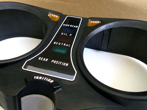
Next: Gear indicator.
 
I made a boo boo when testing the circuit on the gear indicator and blew the circuit board up... Oh well, I like my method a little better.

I cut a chunk of PCB from radio shack to fit the same dimensions as the stock board.

GS85064.jpg


I used small (3mm) high intensity LEDs since I had them laying around. The housing for the bulbs is deep, so I cut shrink tubing to 7/32" for spacers to keep the LEDs up higher in the housing.

GS85066.jpg


Fortunately the holes fell right in line with the housing, so getting the lights to line up was easy. Soldered them in, and then straightened them out.

GS85067.jpg

GS85069.jpg

GS85070.jpg

GS85074.jpg


I lined up the 1st-5th wires and soldered them in to place. I installed a single in line resistor and bridged the source wire across all 5 LEDs with some 18ga hookup wire.

GS85076.jpg

GS85077.jpg


I don't have a picture of the end result, but they look great and the housing fits just like normal.

Next: Idiot lights.
 
May be a little bit overkill, but this is my plan for LED idiot lights...

GS85081.jpg


More to come tomorrow.
 
Love your work! Definitely keener than me with the gauge backlights, but the spread of light with your method is far more even as I have a few darkish spots.

Nice work on the gear indicator circuit board too :eek:

Looking forward to see how you finish it off, but looks like you'll end up with a nice bit of quality work there for sure.
 
Hi,

Nice upgrade project! Thanks for sharing. You do good work.


Thank you for your indulgence,

BassCliff
 
Well done! If I have to work on mine I may look at approaching it form this angle next time! I wonder what amber LEDs would look like as back lights?
 
Ive found in some of the bikes ive owned/worked on RED bulbs...might be worth trying some red LEDs to keep the stock look?
 
Ok, I'm doing this one next time I'm into the clocks :)

How about a few different color LED's just for fun :D
 
i like what you did with the gear indicator but as for the rest why not just replace the bulbs with led bulbs you can get them here->http://www.superbrightleds.com/cgi-...tion=DispPage&Page2Disp=/tail-brake-turn.html

Aside from tools and time, this entire project cost me a grand total of $8.50. Plus it's fun to mess around and make something no one else has. That, and USPS was taking wayyyyy to long to get to my house with parts, so I got antsy.

As far as tail and signal bulbs, I have some stalk mount LED signals I'm going to use, and the tail will eventually be an early 2000s gsxr with an integrated LED tail light.
 
GS85082.jpg

GS85083.jpg

GS85085.jpg

GS85087.jpg


Hoping to have it all back together tonight. The stupid cheap board I got from radio shack kept having the copper dots separate from the board, so I had to chop off the bottom of the "T" and cut a little 3/4" square for the bottom light. Oh well it all worked out.

I was going to mention earlier, but I use Shoe Goo and a cheapo acid brush to seal off the connections to prevent arcing and corrosion. Just squeeze it on there and use the brush to make sure it gets all over the connection. Primitive, but works very very well.
 
Certainly looks the goods! Looking forward to seeing it together and in action.

I got some batteries for the camera but I've had a few too many this evening to get down to the garage and get some pic's of mine in action...
 
Wanted to drag this out of the bowels of the forum to ask some questions if you don't mind.


You said the cheap board you got from Radio Shack caused problems. What do you mean by that? What's the recommended way around what you experienced?

How does this compare with Matchless' writeup in Basscliff's site? Which way is easier/better?

Any other advice?

Sorry for the dump questions but I'm trying to figure out how I want to go with some of my changes.
 
Last edited:
the Radio shack "bread board" pcb he was using has small copper plated rings encircling each one of the little holes. This is so the components have something to attach to on the board when making connections. As he was soldering his components onto the board, the copper ring would flake off or otherwise lift off of the board rendering that particular hole virtually useless.

Very frustrating when soldering multiple components to a particular section of a board :cry:
 
And one more year later, a resurrection.

I found this while researching for my current project of building a custom dash. I am ditching the factory idiot lights for LED ones (Thought about converting the illumination bulbs like was done in this thread, too, before I discovered this. Glad someone else has proven success, already.).
As of tonight, I have the LEDs mounted and so far all is going well, but then a question hit me: Am I going to have to do something about the turn signals and their flashing rate now that the indicators are now LEDs, much like when you convert to actual LED turn signals? Is my flash rate now going to be screwed up? I didn't notice this mentioned in here, but that doesn't mean it had to be addressed. I plan on conventional turn signals, just the dash indicators will be LED.
Any help is appreciated.
 
i
And one more year later, a resurrection.

I found this while researching for my current project of building a custom dash. I am ditching the factory idiot lights for LED ones (Thought about converting the illumination bulbs like was done in this thread, too, before I discovered this. Glad someone else has proven success, already.).
As of tonight, I have the LEDs mounted and so far all is going well, but then a question hit me: Am I going to have to do something about the turn signals and their flashing rate now that the indicators are now LEDs, much like when you convert to actual LED turn signals? Is my flash rate now going to be screwed up? I didn't notice this mentioned in here, but that doesn't mean it had to be addressed. I plan on conventional turn signals, just the dash indicators will be LED.
Any help is appreciated.


Will not change anything.

Those original lights draw very little power anyways.

You could just get an LED flasher to replace yours and have the option of using any lights you want and a constant flash rate no matter the load.
 
Last edited:
Am I going to have to do something about the turn signals and their flashing rate ... I plan on conventional turn signals, just the dash indicators will be LED.
Any help is appreciated.
Do you have a single indicator on your bike or do you have one for each side?

If you have one for each side, you should have no problems.

If you have a single indicator, you will have to add a couple of diodes and do just a little re-wiring.

.
 
Do you have a single indicator on your bike or do you have one for each side?

If you have one for each side, you should have no problems.

If you have a single indicator, you will have to add a couple of diodes and do just a little re-wiring.

.

There's mention of a 78, 750 in his previous posts.
 
There's mention of a 78, 750 in his previous posts.
That's nice, but I don't have one of those handy to know whether it has one indicator or two.
icon_shrug.gif


There is nothing in his signature for me to see NOW, and I'm simply too lazy to bother looking up "previous posts". :p

.
 
That's nice, but I don't have one of those handy to know whether it has one indicator or two.
icon_shrug.gif


There is nothing in his signature for me to see NOW, and I'm simply too lazy to bother looking up "previous posts". :p

.

Were in the same boat :P I was hoping you would say: hey yeah I know exactly what that bike has :cool:

Usually the first post anyone makes has the bike info.

Guessing its this type, Should be a nice and easy mod.
P4080322dd9.jpg
 
Back
Top