• Required reading for all forum users!!!

    Welcome!
    Register to access the full functionality of the GSResources forum. Until you register and activate your account you will not have full forum access, nor will you be able to post or reply to messages.

    A note to new registrants...
    All new forum registrations must be activated via email before you have full access to the forum.

    A Special Note about Email accounts!
    DO NOT SIGN UP USING hotmail, outlook, gmx, sbcglobal, att, bellsouth or email.com. They delete our forum signup emails.

    A note to old forum members...
    I receive numerous requests from people who can no longer log in because their accounts were deleted. As mentioned in the forum FAQ, user accounts are deleted if you haven't logged in for the past 6 months. If you can't log in, then create a new forum account. If you don't get an error message, then check your email account for an activation message. If you get a message stating that the email address is already in use, then your account still exists so follow the instructions in the forum FAQ for resetting your password.

    Have you forgotten your password or have a new email address? Then read the forum FAQ for details on how to reset it.

    Any email requests for "can't log in anymore" problems or "lost my password" problems will be deleted. Read the forum FAQ and follow the instructions there - that's what we have one for...

  • Returning Visitors

    If you are a returning visitor who never received your confirmation email, then odds are your email provider is blockinig emails from our server. The only thing that can be done to get around this is you will have to try creating another forum account using an email address from another domain.

    If you are a returning visitor to the forum and can't log in using your old forum name and password but used to be able to then chances are your account is deleted. Purges of the databases are done regularly. You will have to create a new forum account and you should be all set.

LED wiring

  • Thread starter Thread starter afholderman
  • Start date Start date
A

afholderman

Guest
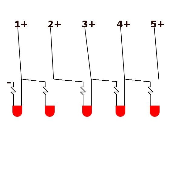
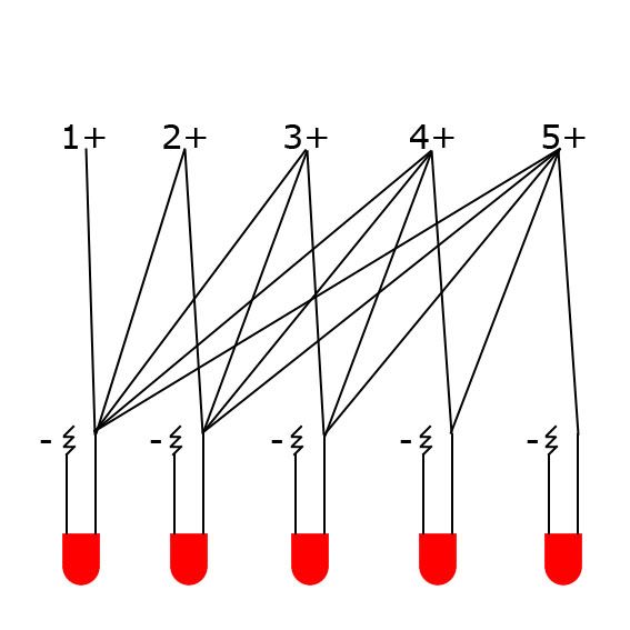
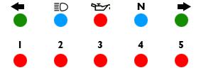
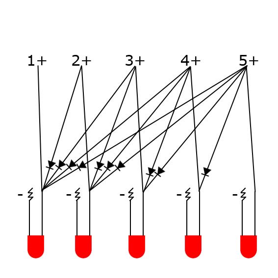
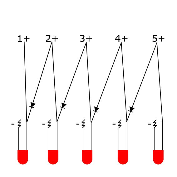
Soon I will be changing out my gauge cluster for a mini tach and speedo set from partsnmore.com. I am going to fabricate a small dash of LED light that mounts on top of the handle bar clamps. The dash will have two rows of 5 LED's, the top row LT, Hi-beam, Oil Pressure, Neutral, RT, and the bottom the 5 gear lights. I know the gear lights aren't necessary, but I like the aesthetic of two even rows of LED's, plus I don't want my supposed upgrade to actually lose my bike any degree of functionality. I have a question though concerning the wiring for the gear indicator. It would be simple enough to wire them one for one in the harness, but I would like to go a different route. Instead I would like the lights to add up, as in one light for first, two for second, etc. Since they are diode's would the below diagram function in this way? If not hopefully someone on here will have a little insight on how to complete this project. Thank you.

LED.jpg
 
In that arrangement, you'll have all the LEDs and resistors in series when 5 is energized. They will be dim, if lit at all. The LEDs have significant voltage drop when lit, so any series arrangement would have to account for that. I think you're going to need to use separate diodes to get them to light. I don't know whether the extra diodes will cause enough voltage drop to cause uneven lighting. You might need to use the diodes to feed transistors in saturation to switch the LEDs on instead. That might be your best bet for even lighting and the behavior you want.
 
I have a new drawing using the tool located here: http://led.linear1.org/led.wiz. With the specs from superbrightleds.com's 360 degree viewing angle LED's here it is for 5 in series with 12v power.
5LEDseries.jpg


I also checked the drawings for 1-4 LEDs, and they are exactly the same, minus the difference in lights. So it appears that my original drawing was incorrect in the use of multiple resistors, instead I only will need 1 100ohm at the end of the series. Would I also need to use separate diodes to keep from reaching the reverse voltage limits of the LED's?
 
Last edited:
I have a new drawing using the tool located here: http://led.linear1.org/led.wiz. With the specs from superbrightleds.com's 360 degree viewing angle LED's here it is for 5 in series with 12v power.
5LEDseries.jpg


I also checked the drawings for 1-4 LEDs, and they are exactly the same, minus the difference in lights. So it appears that my original drawing was incorrect in the use of multiple resistors, instead I only will need 1 100ohm at the end of the series. Would I also need to use separate diodes to keep from reaching the reverse voltage limits of the LED's?

Well, I think you'd have to look up the specs for the LED you plan to use. I'm not sure what's typical for them.

I think I see where you're going. You may not need the extra diodes after all.

If the diagram you show is for 5th gear, then adding 4th would require a resistor connected to ground between the leads of the last two LEDs. The resistor for 4th would need to create a voltage drop equivalent to the 100 Ohm resistor and the 5th gear LED in series. 3rd would be similar, with a resistor sized to make the same voltage drop as the 100 Ohm resistor and the 4th & 5th gear LEDs. And so on.

The problem I anticipate is finding resistors with appropriate values to get the equivalent voltage drops. If you do find some of the right values, they might have a 20% tolerance on the values. That might give you noticeably different brightness in the LEDs. You could maybe to it with some small potentiometers, in which case you could balance them like carbs. oh boy.

It's worth a shot. You can always fall back to one light per gear.
 
It's worth a shot. You can always fall back to one light per gear.

Exactly. I just want to do this as a fun little project. If it works I get something unique, if not, no harm no foul.
 
What about something more like this, splitting the power before it reaches the LEDS? That way each one would just be treated as a single LED receiving 12v and resisted accordingly.
NewLED.jpg
 
to me last one makes the most sense but aren't you forgetting the most important one?


(neutral)
 
to me last one makes the most sense but aren't you forgetting the most important one?


(neutral)


Neutral is going in the top row center and will retain it's stock functionality, so wiring it will be no problem.
 
ok so i just looked at wiring diagram it shows that basically every light is wired individualy and gear position sensor sends the signal only to one bulb at a time, in your last diagram you did it right if you want to light them up in a sequence of number of led's per gear 1 led 1st gear, 2 leds 2nd gear etc. now u just gotta figure out which led's to use to calculate the right resistors.
my only concern is when the gear switch is say in 3rd gear the positive lead gets the juice but with your wiring you are also sending juice back to 2nd and 1st leads in the switch i dont know enough to know if this will damage the switch or not.
 
No, even more important than that pesky neutral light, ...

The stock indicator lights are fed by a constant HOT wire and switch the grounds. :o

.
 
ok
leds work off of amperage
not voltage
the resistor limits the amount of amperage the led takes

too low a resistor and the led will burn out
too high a resistor and the led will be dim

you will always need a resistor for each light

the best way would be to wire each led and resistor as its own unit, yes that means 1 led and 1 resisor per gear

this way when you want them all to light up in 5th, you just power each of the circuits

if you ty to power all of them through 1 resistor, you either will have too little or too much resistance
meaning
the system, the resistace of the resistor is specific to the load
which is specific to the requirements of the led

1 led requires a differnt amount of power then an entire row of leds
so if you calculate it out for 5, your resistor is there properly for when all 5 are lit
if you just try to power 1 with that same system, you will blow the led due to too much amperage

if you use each as its own system

led-re
led-re
led-re
led-re
led-re

then you can just tie into each controled system saftely and brightly
 
you will always need a resistor for each light

The zig-zag lines in the drawings indicate resistors, so in the last diagram there would be a resistor for each light as you indicated
No, even more important than that pesky neutral light, ...

The stock indicator lights are fed by a constant HOT wire and switch the grounds. :o

.

This does present a problem. What mechanism is used to switch the grounds?

To re-iterate, neutral is not being left out of the picture. As stated in the original post, I am planning for two rows of 5 LEDs. Neutral would be in the upper row, and as it would not be lighting in this sequence is not being dealt with in the diagrams. Something like this:
DashLayout.jpg
 
Last edited:
This does present a problem. What mechanism is used to switch the grounds?
The mechanism to switch the grounds is down under the cover by your left foot.

Pull the shifter lever off, then the four bolts that hold the cover, you will see the gear indicator selector switch.

.
 
What about something more like this, splitting the power before it reaches the LEDS? That way each one would just be treated as a single LED receiving 12v and resisted accordingly.
NewLED.jpg

Um. That's going to light every one of them whenever you're in any gear. Except for what Steve said.
 
Um. That's going to light every one of them whenever you're in any gear. Except for what Steve said.

Okay this would take care of them lighting in every gear, but also these diagrams assumed that power was switched, not ground.

NewLED2.jpg

So if I am to understand correctly, all of the lights have constant power with a ground leading to the switch, and when the gear lever is in the correct position it closes the circuit lighting the bulb? If this is the case would it be possible then to reverse the wiring, with power wires leading through switch and then using the above diagram?
 
Last edited:
The stock indicator lights are fed by a constant HOT wire and switch the grounds. :o

.

I've always been intrigued by that - what's their logic for doing it that way? It's not just Suzuki or even just motorcycles - auto makers do it too. What's the advantage over switching the hot side?
 
Okay this would take care of them lighting in every gear, but also these diagrams assumed that power was switched, not ground.

NewLED2.jpg

So if I am to understand correctly, all of the lights have constant power with a ground leading to the switch, and when the gear lever is in the correct position it closes the circuit lighting the bulb? If this is the case would it be possible then to reverse the wiring, with power wires leading through switch and then using the above diagram?

OK, that would work, but you only need one diode between each gear. The electricity will be able to flow all the way from 5th back to 1st through the sting of diodes. It should also be possible to reconfigure for the opposite polarity.
 
OK, that would work, but you only need one diode between each gear. The electricity will be able to flow all the way from 5th back to 1st through the sting of diodes. It should also be possible to reconfigure for the opposite polarity.


More like this then:
NewLED3.jpg


Anyone have opinions on whether to use wiring or etch a circuit board?
 
Yeah, that's it. Just reverse the polarity and diodes.

How are you planning to mount the LEDs? For a circuit this simple, I wouldn't think you'd have to make a board. Just pot it in epoxy after it's working. That's just to protect it from vibration damage. I think that might be a good idea if you make a board too.
 
Back
Top