• Required reading for all forum users!!!

    Welcome!
    Register to access the full functionality of the GSResources forum. Until you register and activate your account you will not have full forum access, nor will you be able to post or reply to messages.

    A note to new registrants...
    All new forum registrations must be activated via email before you have full access to the forum.

    A Special Note about Email accounts!
    DO NOT SIGN UP USING hotmail, outlook, gmx, sbcglobal, att, bellsouth or email.com. They delete our forum signup emails.

    A note to old forum members...
    I receive numerous requests from people who can no longer log in because their accounts were deleted. As mentioned in the forum FAQ, user accounts are deleted if you haven't logged in for the past 6 months. If you can't log in, then create a new forum account. If you don't get an error message, then check your email account for an activation message. If you get a message stating that the email address is already in use, then your account still exists so follow the instructions in the forum FAQ for resetting your password.

    Have you forgotten your password or have a new email address? Then read the forum FAQ for details on how to reset it.

    Any email requests for "can't log in anymore" problems or "lost my password" problems will be deleted. Read the forum FAQ and follow the instructions there - that's what we have one for...

  • Returning Visitors

    If you are a returning visitor who never received your confirmation email, then odds are your email provider is blockinig emails from our server. The only thing that can be done to get around this is you will have to try creating another forum account using an email address from another domain.

    If you are a returning visitor to the forum and can't log in using your old forum name and password but used to be able to then chances are your account is deleted. Purges of the databases are done regularly. You will have to create a new forum account and you should be all set.

Schematic and guide to fit relays

  • Thread starter Thread starter Matchless
  • Start date Start date
Thanks for the PDF... has got me thinking. I will most likely just put a couple in for the coils but I may go the whole hog....

Cheers,

Dan :)
 
Thanks mate!
I just did the coil mod and it worked a treat.
Also changed my fuseblock for a bladefuse block.
I will take some pics when I have my camera.
Cheers
 
Hi KiwiGS,
Glad it has helped. Please let us have the pictures as my own modification is still pending for a few months.
 
Matchless: Great writeup. I have questions about the ignition coil relay. I have the same 5 pin relay as yours.

Why should the relay be close to the coils? I put mine on the side of the battery box.

I'm confused (which is normal) about the orange/white wires on the coils. The two original o/w wires on the coils go to inputs 87 on the relay, with new connectors.

"Cut the plugs off the killswitch side of the o/w wires, connect one wire to pin 86 and sleeve/wrap the other one". Where do I find the killswitch side????
 
The kill switch wire comes down from the handlebar (obviously) & joins into the main loom via one of the multi plugs there, about 6" back from the neck of the frame.

By Kill switch side I presume he means cut them before they hit the multi plug.

No reason you can't have your relays back there.... the wire runs all become much longer though (although the battery +12v to Relay runs will be shorter).

Dan :)
 
Last edited:
Salty has already replied and covered all the points.
Basically you are just using the positive wire that powered your coil when the ignition and killswitch was on to operate the relay. As Salty also said putting it close to the coils allows you to use the same wire without having to lengthen it. This then means that only your new battery wire runs all the way from the battery box.
If you fit the relay on the battery box, you would have to extend the wire back to the relay and still run the new battery feed to the coils from the relay contact, so two long wires. Not a problem it will still do the job.


I have just replaced my fuse block for a 8 fuse one, that makes these extra dedicated feeds to the relays easier.
 
I will try later but the link on the first page to download the .pdf file is not working for me. It just stops with no explaination.
 
Just a quick note on the waterproofing issue. With these plastic relays it is actually pretty easy to waterproof them yourself. Just use some high temperature silicone sealant (Form-A-Gasket works great for this) and a popsicle stick to seal up all the crevices where water could seep in, or even coat the entire bottom of the relay to be extra sure.

Just remember to make a note as to which terminals are which, since you'll be covering the identifying numbers with silicone when you waterproof the relay.

Although waterproofing the relay probably isn't necessary, it will prolong the life of the internal contacts over time and save you having to replace the relays as often.

Regards,
 
Cool looks good! What'd you do to gang your inputs together?

J_C,
I just bent the spade terminals in the same direction, wrapped some heavy copper wire around them and soldered. I then covered that with black silicon rubber inside a small channel bent up from the baseplate. The spade terminals have also been soldered permanently in place.
The extra fuses are for the coil, horn and headlight relay and a 12 Volt jack.
 
Well I have to say that I did the coil relay ad WOW what a difference in how it starts and runs. I did decide that after last weekend incident I am going to wire my bike so it won't run if the side stand is down. I found that the bulb burned out on my dash the hard way. I'll be making the change when i replace my guages, windshield, mirror, gas tank, and trunk. (that's the list so far)
 
I had a 2.9 voltage drop between the battery and coils. I just finished the coil mod and it's only a .2 volt drop !!!
 
J_C,
I just bent the spade terminals in the same direction, wrapped some heavy copper wire around them and soldered. I then covered that with black silicon rubber inside a small channel bent up from the baseplate. The spade terminals have also been soldered permanently in place.
The extra fuses are for the coil, horn and headlight relay and a 12 Volt jack.

Nice, looks good man. I've been trying to find a ganged 8 fuse panel that is vertical and easy to fit like that, just haven't been able to locate it yet. Your way should work just fine if I can't :)
 
Could someone give me a clue as to how to get the file to download from the link on the first page?
 
I guess I was the only one having trouble. I finally downloaded it. Maybe it was because I am using Firefox or my setup, but I ended up clicking on the download file box which looked like it was working but the PDF file would stop loading and would show nothing. I "saved page as" the stopped blank page to a folder on my computer and then it downloaded just fine :confused:

Thanks, Matchless! It is a great bit of instruction.
 
Last edited:
I should have followed this up when the first report came to me.:oops: I now also tried downloading and found that I cannot download any of my PDF files any more. The other files seem OK. I have submitted a trouble ticket to MediaFire and hopefully they will reply soon.
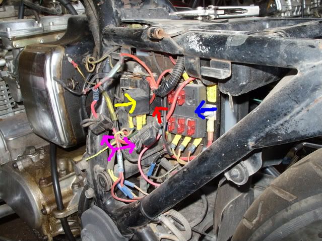
Will let you know when its working again, but in the meantime please try the method used by GSJohn
 
For Firefox users there is an excellent FREE add-on for downloading called "Download Them All."

I also had problems with the Mediafire link, but after right clicking on it and selecting the "Download Them All" option not only did the download work perfectly but it went MUCH faster than typically happens. I used this add-on a few days ago to download a 1.5 GIG GPS map/firmware upgrade for one of my GPS's, and what supposedly would take about eight hours (by the website's estimation) was finished in three. Very nice tool!

CLICK ME FOR DOWNLOAD THEM ALL - FIREFOX ADD-ON

Hope this is helpful!

Regards,
 
here is the ignition relay on my 1100E
001-2.jpg


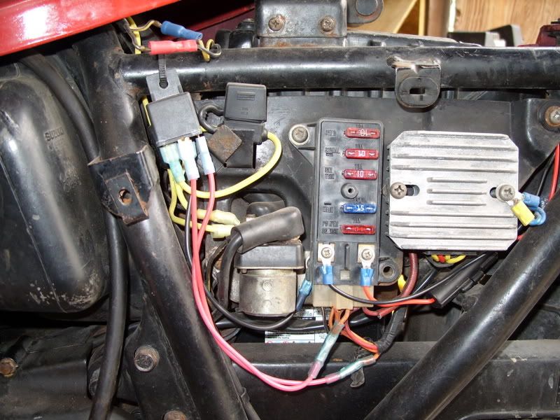
excuse the mess (need to do some cleaning up) this is the ignition relay and horn relay(in front of ignition relay) on my 80 1000G, this is also the aftermarket fuse panel, I did this a couple years ago and it has not missed a beat.

you can also see the inline fuse holders for the main relay and the headlight power relay

005-6.jpg


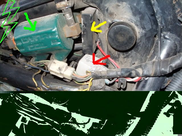
the gray object is the headlight switchover relay and controls low and high beam, the ignition relay controls power to the 30 terminal of the switchover relay.

this is mounted under front of tank in front of coils on right side and is a epoxy sealed water proof relay.
the black box in front of the coils is a integrator module and allows the front turn signals to act like running lights (dim) and turn signals (bright) using the standard single filament bulbs.

007-4.jpg
Hi focus
In your third picture you show an integrator module for your turn signals--what kind is it and where can I get one?
 
Back
Top