• Required reading for all forum users!!!

    Welcome!
    Register to access the full functionality of the GSResources forum. Until you register and activate your account you will not have full forum access, nor will you be able to post or reply to messages.

    A note to new registrants...
    All new forum registrations must be activated via email before you have full access to the forum.

    A Special Note about Email accounts!
    DO NOT SIGN UP USING hotmail, outlook, gmx, sbcglobal, att, bellsouth or email.com. They delete our forum signup emails.

    A note to old forum members...
    I receive numerous requests from people who can no longer log in because their accounts were deleted. As mentioned in the forum FAQ, user accounts are deleted if you haven't logged in for the past 6 months. If you can't log in, then create a new forum account. If you don't get an error message, then check your email account for an activation message. If you get a message stating that the email address is already in use, then your account still exists so follow the instructions in the forum FAQ for resetting your password.

    Have you forgotten your password or have a new email address? Then read the forum FAQ for details on how to reset it.

    Any email requests for "can't log in anymore" problems or "lost my password" problems will be deleted. Read the forum FAQ and follow the instructions there - that's what we have one for...

  • Returning Visitors

    If you are a returning visitor who never received your confirmation email, then odds are your email provider is blockinig emails from our server. The only thing that can be done to get around this is you will have to try creating another forum account using an email address from another domain.

    If you are a returning visitor to the forum and can't log in using your old forum name and password but used to be able to then chances are your account is deleted. Purges of the databases are done regularly. You will have to create a new forum account and you should be all set.

Stator Papers Clarification

  • Thread starter Thread starter Gibbelstein
  • Start date Start date
G

Gibbelstein

Guest
Hi All,
I recently replaced the stator in the 850 and it does not seem to be charging. I am trying to run through the Stator Papers and I need a little clarification. I had the meter on the battery and it is reading 11.7 at all rpm, so I am thinking that it is just running off the battery because it was reading 12.3 the other day when I tested it but didn't have time to tear into it.

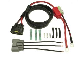
I am trying to check resistance across the three yellow wires but when I installed it, I used the butt splices that came with the kit I got at RoadsterCycle.com (I also installed a Shindengen SH775 at the same time because I guess I like to complicate things where possible.)

My clarification is: When I checked the resistance, I get a 0.00 for all three tests and I am wondering if that might be because it is 'backtracking' through the R/R instead of going through the stator? I am going to put blade connectors on instead anyway so I can test it properly soon enough, but I was wondering whether the outcome for when I put on the new connectors was a foregone conclusion so I could start planning accordingly.

On a related note, I was able to test the old stator because it was out already and I got the same result (no resistance on all three pairs). Am I correct in thinking that this means the old one is completely bad?

Thanks for any insight you can give.

—Chris
 
Last edited:
Hi,

There is a stator testing "how to" guide on my little website.


Thank you for your indulgence,

BassCliff
 
My clarification is: When I checked the resistance, I get a 0.00 for all three tests and I am wondering if that might be because it is 'backtracking' through the R/R instead of going through the stator? I am going to put blade connectors on instead anyway so I can test it properly soon enough, but I was wondering whether the outcome for when I put on the new connectors was a foregone conclusion so I could start planning accordingly.

The resistance should be checked with the stator disconnected from the R/R. Take your measurements at the three wires that come off the stator. You want to see a value between 0.5 - 2 ohms. If you are really showing 0 ohms then your stator is defective.

Before you start any testing you need a fully charged battery. 12.3 volts is not fully charged. I would want to see a voltage closer to 12.6 for a fully charged battery.

I use this flow chart and have found it helpful
http://www.electrosport.com/media/pdf/fault-finding-diagram.pdf
 
Check your multimeter - some units can't read resistances this low- and low batteries also can produce strange readings.
 
Resistance is ALWAYS checked with the part(s) isolated.

Disconnect it or you will be reading dead shorts because the diodes in the rect/reg are being read also...
 
Do a quick test first:

http://www.thegsresources.com/_forum/showthread.php?p=1272192#post1272192


Revised Phase B to improve probability of finding the problem.

And here are some updates with background to the Phase B tests that focus on the stator alone.

A revised test is at this link; The actual test is on Page 6 of 9. We added the leg to ground AC voltage test as this helps isolate insulation breakdowns to ground using the relatively high 60-80 VAC stator voltage when it is open loop.

Link to Revised PHASE B of Stator Pages with discussion of testing methods:
http://www.keepandshare.com/doc/3977567/dummy-load-scanned-pdf-may-14-2012-8-24-pm-649k?da=y
 
Hey, thanks, gang. That pretty much confirms what I was thinking.
1) I will test the new stator when I put the new connectors in.
2) My old stator is dead (I'll try to check my meter to make sure it's accurate)
3) Posplayr: That was the beginning test I as trying to do. The battery is charging right now, so I'll write down all of the readings. I didn't do the full test, but I do know this time that the readings were all 11.7 at idle, 2500, and 5000.

Thanks again guys,
Chris
 
Just wanted to add that it's critical to bypass the old factory wiring when installing your new stator and R/R. Wire the stator directly into the R/R, do NOT connect to the old GS harness connectors since the current path is convoluted and indirect (lots of harnesses melt down due to too much path resistance). Also make sure the R/R has a solid frame or battery ground path. Never ground to the battery box or the rubber mounted electrical side panel like Suzuki sometimes did on the GS's.
 
Thanks, Nessim. That's most of the reason that I got the Roadster Cycle kit (pic here:
Super_harness_cb_wb_irf.jpg
or here: http://roadstercycle.com/images/Super_harness_cb_wb_irf.jpg

The stator is wired directly to the grey harness and the black and red leads are connected directly to the battery. I hadn't considered making an additional path to ground, but I think I will add another ground to make sure that the grounding is sufficient for all purposes, not just this. So, Thanks.

It does make me wonder whether insufficient grounding could be preventing it from charging properly?

Side note: I am going to have to pull off the cover again to replace the gasket. Is there any more thorough testing that I can do when I get in there, besides just a visual inspection? Or is checking resistance externally the only test that can be done to a stator anyway?

Thanks for the great help, as always.

Chris
 
I have seen improved grounding restore marginal charging to excellent charging. I have also seen improved grounding make no change to marginal charging performance.

I normally run a wire from the battery box ground to the battery and the frame.
 
Side note: I am going to have to pull off the cover again to replace the gasket. Is there any more thorough testing that I can do when I get in there, besides just a visual inspection? Or is checking resistance externally the only test that can be done to a stator anyway?
Externally, you can check resistance and voltage output.
For both of these tests, the stator needs to be disconnected from the R/R.

Internally, it's just a visual inspection.

.
 
Hey, thanks, gang. That pretty much confirms what I was thinking.
1) I will test the new stator when I put the new connectors in.
2) My old stator is dead (I'll try to check my meter to make sure it's accurate)
3) Posplayr: That was the beginning test I as trying to do. The battery is charging right now, so I'll write down all of the readings. I didn't do the full test, but I do know this time that the readings were all 11.7 at idle, 2500, and 5000.

Thanks again guys,
Chris

A low battery will hold the R/R charging voltage down, which is why it is recommended to always test with a fully charged battery. On the other hand when the R/R output basically flatlines as your is then it appears to not be charging at all. Even though it is not a complete Quick test, you should probably move to Phase A.

A quick check using the Modified Phase A of the stator pages will confirm if there is any current flow from the R/R. If there is, then there will usually voltage drops at the ground and + side of the battery (see the flow chart). If the battery voltage is low and there are no voltage drops then there is no current flowing from the R/R.

Moving to the Phase B stator tests, even though generally inconclusive it is high likely the stator is bad and you are just looking for a confirmation of the same.
 
additional test

additional test

Hi,

Another test you could do is an unloaded stator test. This test is done by disconnecting the plug closest inline to the stator. Start your bike and Set your meter on V/AC and check the AC output, on the stator side of harness, put one probe on one lead and one on another and test each leg of stator, should be three tests. I would assume the V/AC should be over 90 V/AC o neach leg, if one or more of your stator leads are not producing 90 or over id say your charging system is not performing to the max.

Also while do the test you want to raise RPM up to about 3-5,000 RPM, different stators produce different outputs at different RPM

Do not touch them together, you will get a good spark, the test is done using V/AC because the current produced is AC until it gets the The rectifier which converts it to DC then goes to the battery.

Thanks, Jesse
 
Last edited:
Well, damn. I got to put the new connectors on the stator wires today, but before I could check the VAC on any of the legs, I checked the resistance on the three stator legs and got the same result: zero for all three checks. So, no point in me checking the output, I guess.

I was going to pop off the cover to replace the now leaking gasket anyway, so I'll be in there to check out the 'new' stator. This is a bummer, because I bought it from the Caltric ebay store in December so it is not brand new, but it probably has less than 2hr of use on it and I now suspect that none of that time has it been producing any juice. I contacted them about warranty info.

Thanks again for the input, guys.

—Chris
 
Well, I worked out that the replacement stator was bad, and now I have a new one in hand. In moving on to the next step on the stator papers, I would like to check the new stator before putting it in. I checked the 3 legs against each other, and they are all at 1.0 ohms each (within the 0.5 to 2.0 range from the chart). I then checked the resistance of each leg against the 'chassis' of the stator and got no reading (or OL, whatever you want to call it). This is should be the same as testing against the case, right? And as long as I don't nick any of the yellow wires when I install it, things are fine?

I'm still going to re-test it when things are together, I was just curious about the logic of this step of the test. I'm guessing it is to test for the possibility that one of the yellow wires could be grounding to the case but still independent of the other two, so it would not show in the prior step?

Thanks again for the tips, all.

Chris
 
Hi,

When testing for continuity between a stator leg and chassis ground, it should look like an open circuit, infinite resistance (or OL). There should be no connection between a stator leg and ground.

Stator Test (PDF file)

Thank you for your indulgence,

BassCliff
 
Well, I worked out that the replacement stator was bad, and now I have a new one in hand. In moving on to the next step on the stator papers, I would like to check the new stator before putting it in. I checked the 3 legs against each other, and they are all at 1.0 ohms each (within the 0.5 to 2.0 range from the chart). I then checked the resistance of each leg against the 'chassis' of the stator and got no reading (or OL, whatever you want to call it). This is should be the same as testing against the case, right? And as long as I don't nick any of the yellow wires when I install it, things are fine?

I'm still going to re-test it when things are together, I was just curious about the logic of this step of the test. I'm guessing it is to test for the possibility that one of the yellow wires could be grounding to the case but still independent of the other two, so it would not show in the prior step?

Thanks again for the tips, all.

Chris

Yes :clap:
 
Hi,

When testing for continuity between a stator leg and chassis ground, it should look like an open circuit, infinite resistance (or OL). There should be no connection between a stator leg and ground.

Stator Test (PDF file)

Thank you for your indulgence,

BassCliff

Hi Cliff
Very nice write up as usual. I would however suggest adding the additional test of AC voltage to ground on each leg. This will check if there is a short to ground with the AC voltage of the stator applied which is a better test than using the couple of volts that the ohm meter does when checking simple resistance. It is a poor man's Megger if you will. :o

http://www.thegsresources.com/_forum/showpost.php?p=1393931&postcount=4
 
Hey, thanks guys. It looks like things are performing as advertised. Battery holds a charge, and voltage seems to be a steady 14.18v from 2000rpm to at least 5000rpm. And the R/R stays touchably cool when mounted under the battery box.

ALSO:

I'm not sure if this is a tip or if it has already been shared, but I learned that I should test conductivity between the yellow leads and the side cover after the stator has been put in place but before mounting it on the bike. The reason being that I tested the leads to the frame (chassis?) of the stator and it tested fine, but then I tested it against the frame of the bike when it was all buttoned up and it failed (meaning there was conductivity).

After taking things apart and re-assembling them 3 or so times, I found out that one of the coils was close enough to the stator mounting 'tower' on the stator cover that it was only contacting it when things were tightened down. (Before discovering this, tried bending the plate that covers the leads away from the stator.)

So, in case anyone sees this through a search, (and they are able to decipher what I typed above) I thought it might save some people from doing the same task more than once. Test early, test often!

Thanks again, all.

Chris
 
Last edited:
Back
Top