G
Guest
Guest
Today I did a test run with a Vapor on my 82 1100E. I hooked up the tach and head temperature sensor to see if they would work or if the tach would suffer from bounce due to ignition noise. It did. The bar graph read out wasn't too bad and I could probably live with it as is, but the digital RPM display showed the reading bouncing all over the place through a 1000+RPM range. It never seemed to read lower than the Suzuki tach, but was continually bouncing higher. The manual says the bounce should be less than +/-100rpm, so this is not at all correct.
I used the inductive lead wrapped around the plug wire for the signal and went from 7 wraps starting down to 1.5 wraps with no change in the bounce. The black wire on the lead was grounded to a bare spot on the frame so it should have been solid enough to work correctly.
I know some people here have used the Vapor with success and am hoping I can get some tips on how to sort this so I can dump my flaky stock dash and clean up the front end. All experiences/tips/thoughts welcome.
Thanks,
Mark
")

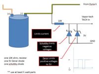
") The zener diode idea was to put it in series, reverse biased, with the tach pickup wire. In theory (or at least in my ignorant head) it would drop 12.1v off the reading, so it would require a spike of 12.1v or more to make it through to the pickup wire.
The zener diode idea was to put it in series, reverse biased, with the tach pickup wire. In theory (or at least in my ignorant head) it would drop 12.1v off the reading, so it would require a spike of 12.1v or more to make it through to the pickup wire.