• Required reading for all forum users!!!

    Welcome!
    Register to access the full functionality of the GSResources forum. Until you register and activate your account you will not have full forum access, nor will you be able to post or reply to messages.

    A note to new registrants...
    All new forum registrations must be activated via email before you have full access to the forum.

    A Special Note about Email accounts!
    DO NOT SIGN UP USING hotmail, outlook, gmx, sbcglobal, att, bellsouth or email.com. They delete our forum signup emails.

    A note to old forum members...
    I receive numerous requests from people who can no longer log in because their accounts were deleted. As mentioned in the forum FAQ, user accounts are deleted if you haven't logged in for the past 6 months. If you can't log in, then create a new forum account. If you don't get an error message, then check your email account for an activation message. If you get a message stating that the email address is already in use, then your account still exists so follow the instructions in the forum FAQ for resetting your password.

    Have you forgotten your password or have a new email address? Then read the forum FAQ for details on how to reset it.

    Any email requests for "can't log in anymore" problems or "lost my password" problems will be deleted. Read the forum FAQ and follow the instructions there - that's what we have one for...

  • Returning Visitors

    If you are a returning visitor who never received your confirmation email, then odds are your email provider is blockinig emails from our server. The only thing that can be done to get around this is you will have to try creating another forum account using an email address from another domain.

    If you are a returning visitor to the forum and can't log in using your old forum name and password but used to be able to then chances are your account is deleted. Purges of the databases are done regularly. You will have to create a new forum account and you should be all set.

Turn signal issue.

  • Thread starter Thread starter groundshock
  • Start date Start date
G

groundshock

Guest
I *think* I got everything wired back up correctly.

Connected all new LED turn signals, replaced flasher with electronic variant.

When I turn the signals on left or right, all 4 turn signals turn on and will not blink. I've got no turn signal light in the cluster either.

Any ideas?
 
You may end up needing some resistors wired in series with the LEDs to trick the circuit into cooperating. The LEDs take so little current to operate that all of them are coming on due to back feeding. Double check wiring, try disconnecting all but one and experiment with resistors to get it to flash.
 
I dont know man, I disconnected all of them and it's the same thing. No turn signal light in the cluster, etc.

I really dont think that its an issue with the LED stuff, but i could be wrong.
 
Hook one of your old ones up(with the others disconnected) and see if the flasher works. If it does...the LEDs are the problem and the flasher needs more circuit resistance to operate. The turn signal light in the cluster will not flash unless the flasher is operating.
 
same crap with either style signal, and either flasher. Dunno man.
 
I would have to say your wiring is not right. Sorry I couldn't help you with that. :cry:
Get a manual. It will help ALOT!
 
I got the wiring diagram, everything seems to be hooked up right. I dunno.
 
My biggest question right now is why when I turn the signals on left or right, ALL the signals come on and stay on.

Turn them on to go left, all the lights come on and dont flash, same with the right.

Turn signal switch shot??? Dont know how, it worked before I disassembled the bike for paint.....
 
if all of your connections are good and secure, then you need a resistor thrown in there because there isn't enough resistance to make the flasher click over. Mine would just turn on and not flash when I had a bad connection to the rear blinkers so only the front ones got power. That wasn't enough to click mine over.
 
But when you flipped the switch to one side, did both sides come on regardless of where the switch was, left or right?
 
sounds like you as said by others....

don't have proper resistor wired in to trigger electronic relay LEDS are either on or off... if it were wired backwards you would get zero... crossed somewhere... and you would know it

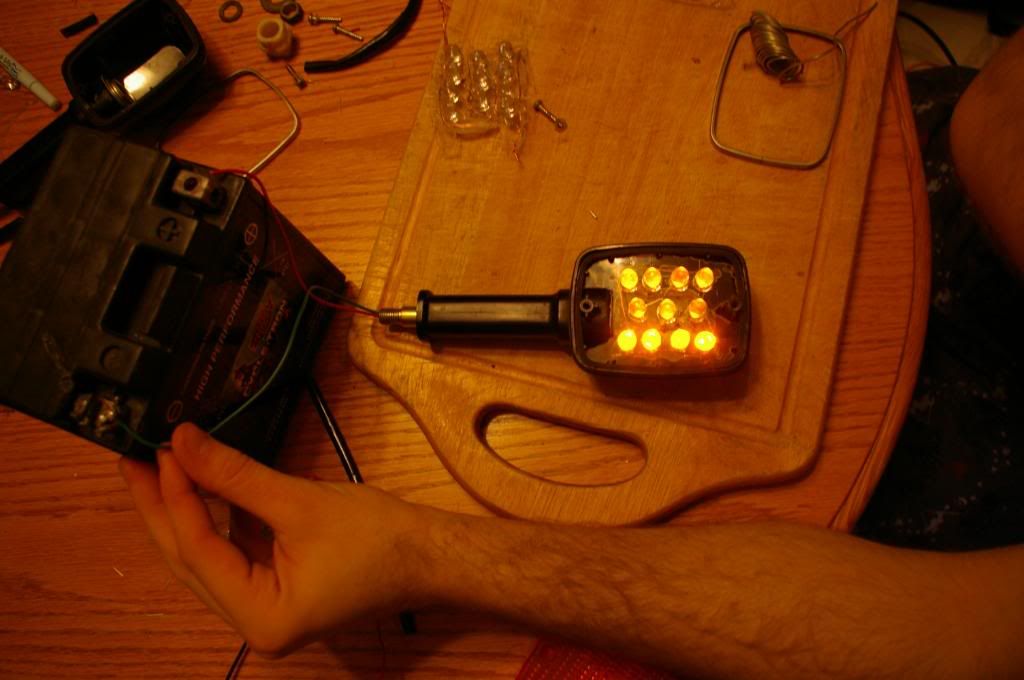
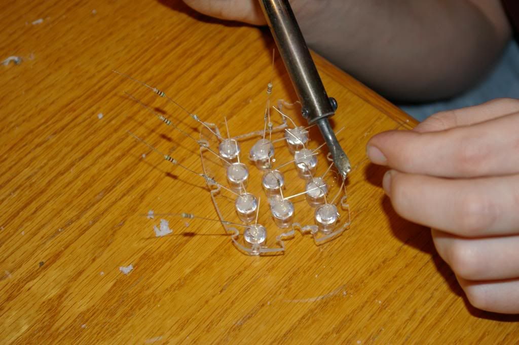
I wired up my LED turn signals and made all the fittings with Tmwnni in weekend two eight hour days.... long time you say... well when you are making everything and I mean everything by hand.. lots of thought and work...then re-working they work for me with a $5 smucks blazer relay... heh.. they had it mismarked by ten dollars

anyway.. if you don't have resistors on them.. put some on the + lead and you should get enough to trip it.

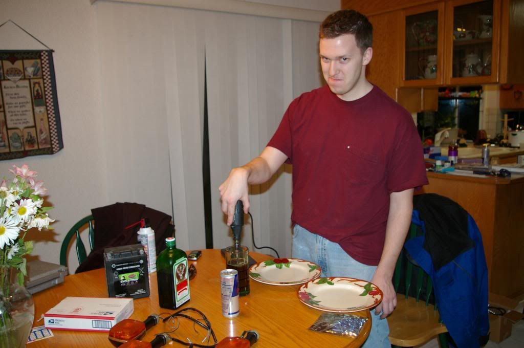
It is all about having the right tools ... and yes I am using my dremel to stir my beverage.... LOL *priceless*

IMGP0571.jpg


IMGP0593.jpg


IMGP0583.jpg


Good Luck
 
Last edited:
Can't really tell you what is wrong, but I agree with Chef . . . sounds like the wiring is wrong or there is an open ground and one set of lights is grounding through the other.
Time to break out the voltmeter. Standard process is to check your voltage levels at all the wiring around the turn signals, both hot and ground. Hot should be 12 volts and ground along with wiring that is turned off should be zero. Then start disconnecting things and measuring until you find the problem.
Disconnect all the turn signal wiring. With the bike off, check the resistance of all the ground connections. Look for any that are not zero. Then turn the bike on and check the hot side of the turn signals, again with them disconnected. Turn the switch on and off, looking for 12 volts to turn on and off, but only on the side that the switch is on for. If everything looks good, connect one set of old turn signals and retest. If everything doesn't look right, start tracing back to the relay and then to the switch itself, disconnecting wires until you find the problem. Make sure you check voltage on both hot and ground circuits as well as on the other disconnected lights. Also, remove and add back the bulbs. Eventually, you will find something that is either mis-connected, shorted or open. Another trick is to disconnect and bypass the switch, and run a test wire directly from the battery (with a fuse), to the relay and to each directional, and then measure the voltages on each individual circuit. You are looking to make sure that each circuit works as expected, and the ones that you are not testing are not active.
Once you get it working with your original lights, re-connect the LED's and then deal with the load problem in order to draw enough current to make them blink.
Let us know what you find.
 
Interesting results.

Took all the wiring apart again. Replaced all the bullet connectors with insulated spade connectors. Everything is hooked up as it should be.

Voltage tests:
1 - at left blinker, switch in center off position - 0.0v
2 - at right blinker, switch in center off position - 0.0v
3 - at left blinker, switch left position, 11.57v steady
4 - at right blinker, switch left position, 10.52v steady
5 - at left blinker, switch right position, 10.53v steady
6 - at right blinker, switch right position, 11.57v steady

What. The. Hell.

I dont have any stock signals to test with. I have NO idea what the hell is going on here.
 
You should have either a green/red or an orange wire going to your turn signal relay. On your bike, I believe it is green/red. This is 12 volts into the relay. Should be a sky blue wire coming out of it. This is 12 volts to your switch. There are two wires coming out of your switch. One is black and brings 12 volts to one set of turn signals and the other is green bringing 12 volts to the other set. Each also brings 12 volts to the appropriate turn signal indicator.
The only thing I see different in the wiring diagram for your bike is that there is only one turn signal indicator light shown. Is that correct? The diagram shows the indicator between the black and green wire coming out of the switch, which doesn't make sense to me since no ground is indicated. However, one has to be there somewhere or else it wouldn't work. So I am guessing that the black wire is supposed to be grounded when the green wire is hot, and vice versa, and that ground connection is probably also in the switch. If that ground was broken, then either directional would turn both sets of lights on, with one set getting 12 volts directly from the switch and the other getting 12 volts through the indicator bulb.
Your voltage readings would seem to support that since the voltage at the directionals opposite to the switch is about 1 volt lower than the voltage to the directionals aligned with the switch.
So either a bad directional switch or a bad ground, I'm guessing to the directional switch. I would suspect the ground. It would be a wire, probably black/white running from the directional switch to frame ground. Just can't explicitly find it in the wiring diagram. But it is the only way that the wiring diagram in the Clymer's manual for your bike makes any sense.
As a test, you might try the following:
With the directional signal, turned to the left, ground the 12 volt wire going to the right directionals. Just touch it really quickly, because if I'm wrong, it's going to spark. But if I'm right, the indicator light should light up, the right directionals should go out, and the left directionals should blink. Then reverse it, turning the directionals to the right and grounding the 12 volt wire to the left directionals. The right directionals should blink. Bottom line, I'm betting that the 'wrong' directionals are getting their 12 volts through the indicator light and not directly from a 12 volt line. So grounding it just lights up the indicator light.
Let us know what you find.
 
Well, those readings were done with the rear signals disconnected. At no point did the turn signal bulb come on, ever.

I connected the rear LED turn signals and these were the results from the identical test:

1 - at left blinker, switch in center off position - 0.0v
2 - at right blinker, switch in center off position - 0.0v
3 - at left blinker, switch left position, 11.07v steady
4 - at right blinker, switch left position, 9.32v steady
5 - at left blinker, switch right position, 9.35v steady
6 - at right blinker, switch right position, 11.07v steady

What I did try was to take a jump wire from the right turn signal hot wire and grounded it to the frame while it was still hooked up to the signal light. More interesting results, as when the switch was on left turn, the relay finally clicked and the right side shut off. It didnt blink, but it wsa some semblance of progress.

I'm leaning towards the whole problem being the LED's, even though I 'assumed' they werent the problem. The electronic flasher did diddly squat. Perhaps finding a solution to using resistors would fix the deal after all?
 
Last edited:
The only thing I see different in the wiring diagram for your bike is that there is only one turn signal indicator light shown. Is that correct? The diagram shows the indicator between the black and green wire coming out of the switch, which doesn't make sense to me since no ground is indicated.
It's actually a rather simple, ingenious arrangement. However, I am not sure it will work with LED signals. In fact, it might be the source of the problem. :shock:

The dash panel indicator is connected across the hot wires of both turn signals. With the stock signals connected, when the left signal is ON, it energizes one side of the indicator bulb. The other side is connected to the hot side of the right signals, but can not pass enough current to light the signals, so the filaments in the signals merely act as ground wires for the indicator. The same thing happens on the right side...the indicator uses the left signals for grounds. Just a side note here...if you were to come up with a method for enabling 4-way flashers, the dash panel indicator would not come on, as both of its wires would either be hot or cold at the same time, it needs a difference to operate.

Thinking through this schematic, it is possible that with the LED signals, the dash panel indicator light passes enough current to make the other side hot, too.
Try removing the indicator bulb from its socket and let us know what you find. 8-[

.
 
GENIUS!

Pulling the indicator bulb allowed the opposite side to shut off! GOOD DEAL!

I wonder if replacing the bulb with an LED variant would solve the issue since the LED wouldnt forward near as much voltage?

Now the only thing to figure out is why they won't blink? Purchased an electronic 3-prong flasher as recommended in other threads but it simply will not flash.
 
Give me a minute or three and I will dig up a schematic for using LEDs for the dash indicators. You will have to use two of them, but you might be able to fashion something with two yellow LEDs in the same space. They don't have to fill the entire yellow lens, as long as they can be seen.

BRB.

.
 
Back
Top