• Required reading for all forum users!!!

    Welcome!
    Register to access the full functionality of the GSResources forum. Until you register and activate your account you will not have full forum access, nor will you be able to post or reply to messages.

    A note to new registrants...
    All new forum registrations must be activated via email before you have full access to the forum.

    A Special Note about Email accounts!
    DO NOT SIGN UP USING hotmail, outlook, gmx, sbcglobal, att, bellsouth or email.com. They delete our forum signup emails.

    A note to old forum members...
    I receive numerous requests from people who can no longer log in because their accounts were deleted. As mentioned in the forum FAQ, user accounts are deleted if you haven't logged in for the past 6 months. If you can't log in, then create a new forum account. If you don't get an error message, then check your email account for an activation message. If you get a message stating that the email address is already in use, then your account still exists so follow the instructions in the forum FAQ for resetting your password.

    Have you forgotten your password or have a new email address? Then read the forum FAQ for details on how to reset it.

    Any email requests for "can't log in anymore" problems or "lost my password" problems will be deleted. Read the forum FAQ and follow the instructions there - that's what we have one for...

  • Returning Visitors

    If you are a returning visitor who never received your confirmation email, then odds are your email provider is blockinig emails from our server. The only thing that can be done to get around this is you will have to try creating another forum account using an email address from another domain.

    If you are a returning visitor to the forum and can't log in using your old forum name and password but used to be able to then chances are your account is deleted. Purges of the databases are done regularly. You will have to create a new forum account and you should be all set.

turn signal question #1,000,006

  • Thread starter Thread starter gregp
  • Start date Start date
G

gregp

Guest
1981 GS750E...I will add to my signature...keep forgetting.
Ok...did some searching but couldn't find anyone that had a similar problem. I have some LED turn signals replacing the stock (no need to be the guy talking me out of it...I read all the arguments in other posts...just need help getting the signals to work properly).
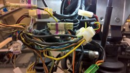
I have bought another relay which seemed to be working. The problem is, I checked one side at a time and each side blinked nicely (and brightly) but when all signals connected they all blink together (left and right) when I turn the signal switch on (L or R). I connected the left and right correctly but I plugged the ground wires (both) into the double bullet ground connector. Looking back at some pictures I noticed that one of the front and one of the rear signals grounds were connected to chassis ground. Why would all of the turn signal blink when I push the turn signal switch L or R? I'm not an electrical engineer but doesn't seem logical that the grounds would have anything to do with this.
 
1981 GS750E...I will add to my signature...keep forgetting.
Just for that, there will be NO HELP until you add your signature. :-\\\


OK, I'll do it. :oops:

Do you have a single indicator on the dash for your turn signals or do you have one for each side? I seem to remember that you also have some sort of check panel, too.

If it's a single indicator, you need to re-wire it with a couple of diodes. The stock signals both connect their hot wires to either side of the single indicator. The single indicator is only going to pass a small amount of current, not nearly enough to light the bulbs on the other side, so it just uses them as ground wires. Your LEDs probably take less current than the single indicator, so enough current goes through that little bulb to light the signals on the other side.

You need to re-wire the socket for the indicator. Instead of having each turn signal feeding indicator, you need to have those wires connected to two diodes that are facing each other (striped ends together). Run a wire from the joint between the two diodes to the indicator socket. Run the other side of the socket to ground.

If you have two indicators on the panel AND the computerized check panel, all bets are off, I don't have a clue how that works. :oops:

By the way, I am not going to talk you out of doing LEDs, I have them myself. :encouragement:

.

thanks Steve!...I have a single indicator (new gauges and the idiot lights have just the single indicator as opposed to the R and L indicator like the stock set up) right now I have the green wire and black wire that come from the main harness that were in the original 6 position idiot light connector connected to the yellow wire from the new gauge (pic in next post...whose the idiot now?)...and the black/white wire from the harness connected to the yellow/black wire. I'm still re-reading your post to decipher where the diodes go...
note:when the idiot lights are disconnected ....same result.
 

Attachments

  • WP_20170215_15_19_53_Rich (2).jpg
    WP_20170215_15_19_53_Rich (2).jpg
    87.9 KB · Views: 0
gauge diagram...
 

Attachments

  • WP_20170309_13_05_52_Pro.jpg
    WP_20170309_13_05_52_Pro.jpg
    85.8 KB · Views: 0
You never mentioned the gauge change in the original post. I had this bike exact same bike and donot recall it having a single turn indication, shiv his what causes the problem. So problem solved.
 
You never mentioned the gauge change in the original post. I had this bike exact same bike and donot recall it having a single turn indication, shiv his what causes the problem. So problem solved.

sorry...the gauge change was something i thought i might have ruled out when i disconnected it. But i am assuming it is related based on your reply. "shiv"...what is that?
 
Do your gauge wires ALL need to be connected, or do they give you the choice of "active HIGH" and "active LOW"?

Your "winker" wires are yellow and yellow/black. I will assume (for simplicity) that the yellow/black is connected to ground. If so, then the yellow wire would connect to the middle of the two diodes I mentioned earlier. Posplayr is right, it would have been VERY helpful to mention that this is not a stock setup on the bike. But since you didn't mention the bike anyway, ... :-\\\
And, the light in your new gauge happens to be an LED, which could change the situation. ALWAYS mention the details.

And you STILL have not put in a signature.
banghead.gif


Here is a rough diagram that should get you started:
turnsignalmonitor.jpg


The setup at the top is your stock setup, with the signals being joined by a single indicator. The lower setup is what you need to do. The wire between the diodes would be your yellow wire.

.
 
sorry...the gauge change was something i thought i might have ruled out when i disconnected it. But i am assuming it is related based on your reply. "shiv"...what is that?

IPhone, auto scramble feature.,"..this is what causes the problem".See Steve's explanation.
 
Do your gauge wires ALL need to be connected, or do they give you the choice of "active HIGH" and "active LOW"?

Your "winker" wires are yellow and yellow/black. I will assume (for simplicity) that the yellow/black is connected to ground. If so, then the yellow wire would connect to the middle of the two diodes I mentioned earlier. Posplayr is right, it would have been VERY helpful to mention that this is not a stock setup on the bike. But since you didn't mention the bike anyway, ... :-\\\
And, the light in your new gauge happens to be an LED, which could change the situation. ALWAYS mention the details.

And you STILL have not put in a signature.
banghead.gif


Here is a rough diagram that should get you started:
turnsignalmonitor.jpg


The setup at the top is your stock setup, with the signals being joined by a single indicator. The lower setup is what you need to do. The wire between the diodes would be your yellow wire.

.

Thanks for your patience...did I mention I'm not an electrical engineer (understatement of the year?)...so according to the GS wiring diagram the stock turn signal indicator for R is the Green wire and for L it is the Black wire. I tied those together and connected to the Yellow wire from the gauge. The Yellow/Black wire from the gauge ("winker -") is connected to the Black/White (gnd) that went to the original gauge panel. This is correct except for adding the diodes?
Your diagram shows my new LED signal light wires for L and R (not the ground wires) connected together with 2 opposing diodes. In between the diodes i should connect to the yellow wire from the gauge with another diode? Is that what i see? sorry...i am a mechanical engineer that thought he didn't have to pay attention in the required basic electrical classes (some 35 years ago).
 
Thanks for your patience...did I mention I'm not an electrical engineer (understatement of the year?)...so according to the GS wiring diagram the stock turn signal indicator for R is the Green wire and for L it is the Black wire. I tied those together and connected to the Yellow wire from the gauge.
Well, electrical engineer or not, if you tied them together, of course they will all come on together, regardless of whether the gauge is connected.


Your diagram shows my new LED signal light wires for L and R (not the ground wires) connected together with 2 opposing diodes. In between the diodes i should connect to the yellow wire from the gauge with another diode? Is that what i see? sorry...i am a mechanical engineer that thought he didn't have to pay attention in the required basic electrical classes (some 35 years ago).

The third diode that you see in the diagram is your indicator in the gauge. (Note the arrows beside the diode, which inicates "light emitting".)
Connect your yellow "winker" wire between the two diodes (banded ends together) and connect the yellow/black wire to ground.

The principle here is that when you have your LEFT signals on, current can still flow through the first diode, but will be stopped by the second one. It can then flow through your indicator to ground.
When you have the RIGHT signals on, the same thing happens, but with the other diode.

.
 
Well, electrical engineer or not, if you tied them together, of course they will all come on together, regardless of whether the gauge is connected.


The third diode that you see in the diagram is your indicator in the gauge. (Note the arrows beside the diode, which inicates "light emitting".)
Connect your yellow "winker" wire between the two diodes (banded ends together) and connect the yellow/black wire to ground.

The principle here is that when you have your LEFT signals on, current can still flow through the first diode, but will be stopped by the second one. It can then flow through your indicator to ground.
When you have the RIGHT signals on, the same thing happens, but with the other diode.

.

Thanks...ran out of time today to get to that but will try this as soon as possible. Hopefully you won't hear from me again on this subject (but doubtful).
 
So I had to sketch this out using the GS wiring diagram as reference so that I could see the bigger picture. I don't want to cut wires that already have pins crimped on unless I'm fairly certain I got this right as my wires are getting shorter with every correction. The confusing thing for me is I can't see all the wires physically...for example, the green and black wires coming from the turn signal light switch goes back under the tank where it must connect to the green and black wires for the front and rear turn signals. It's the whole coming or going thing that I needed to work out in the sketch. I believe I have placed the diodes correctly according to your schematic. If all looks good then I just need to find a couple diodes. I may have some in my shop but not sure if I am looking for any particular diode or not.
 

Attachments

  • WP_20170313_13_45_39_Pro (2).jpg
    WP_20170313_13_45_39_Pro (2).jpg
    85.7 KB · Views: 0
. I believe I have placed the diodes correctly according to your schematic. If all looks good then I just need to find a couple diodes. I may have some in my shop but not sure if I am looking for any particular diode or not.
Diode orientation looks good. You don't need anything fancy, a simple 1N4001 will do just fine.

.
 
Diode orientation looks good. You don't need anything fancy, a simple 1N4001 will do just fine.

.
i have 1N4004 in stock and 1N4148 in stock...
the 1N4004 is rated 400V vs. 50V for the 1N4001...
the 1N4148 specs

  • V[SUB]RRM[/SUB] = 75-100 V — maximum repetitive reverse voltage
  • I[SUB]O[/SUB] = 75-200 mA — average rectified forward current
  • I[SUB]F[/SUB] = 200-300 mA — maximum direct forward current
  • V[SUB]F[/SUB] = 1.0 V at 10 mA.[SUP][13][/SUP]
  • I[SUB]FSM[/SUB] = 1.0 A (pulse width = 1 s), 4.0 A (pulse width = 1 ?s) — non-repetitive peak forward surge current
  • P[SUB]D[/SUB] = 500 mW — power dissipation
  • T[SUB]RR[/SUB] < 4 ns — reverse-recovery time

will one of these or none of these suffice?...which one be would be preferred?
 
You are trying to drive an led bulb in the gauge set I presume which typically only takes about 10-20 amps. So any diode that will safely carry that as a forward current. Every one you mention seems fine. The bigger issue is how are you going to mount it so the wires going great off. Usually that means get something big and husky so you can solder wires right to it and bury into harness.

nice schematic by the way. It warms my cockles to be seeing more and more people real using they need some type of diagram.

Cut and stripped the green wire and black wire and wrapped them around the leads of the diodes... it works!
Now to solder the wires to the leads and cover with heat shrink tubing. I think I will use small heat shrink on either side of the diode to cover the soldered connections and then larger diameter heat shrink to cover the whole thing.
 
Here is a pic of the diodes being soldered in line.... heat shrink in place
 

Attachments

  • WP_20170319_14_52_34_Pro.jpg
    WP_20170319_14_52_34_Pro.jpg
    89.6 KB · Views: 0
Another pic with the heat shrink.... seems fairy robust.
 

Attachments

  • WP_20170319_14_59_58_Pro.jpg
    WP_20170319_14_59_58_Pro.jpg
    96.1 KB · Views: 0
Back
Top