.png "Powered by vBulletin")
I have a question for my 1982 Suzuki GS1100EZ engine.
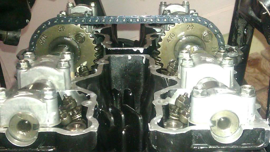
I can't get this thing timed right. It's always off... The notches at the end of each camshaft do not point directly at each other.
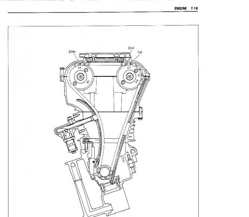
niclpnut provided this diagram, except it came from a GS1000 manual.

My bike has a 451 intake camshaft and a 470 exhaust camshaft.
I did all of my checks when it is aligned with the T mark under the signal generator.

The picture on the left is with the 20 pin setup. The picture on the right is with the 19 pin setup.
Exhaust camshaft.
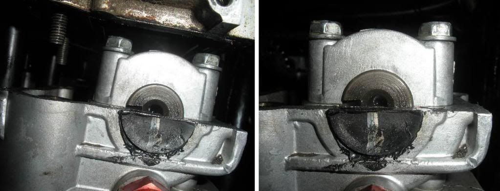
Intake camshaft.
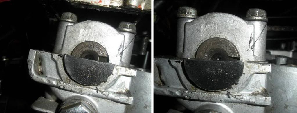
20 pin setup.

19 pin setup.

As you can see, neither setup has it where the camshaft notches point directly at each other. Why? Could my cams be degreed? Or am I being too anal about this whole thing?
Please let me know!
I can't get this thing timed right. It's always off... The notches at the end of each camshaft do not point directly at each other.
niclpnut provided this diagram, except it came from a GS1000 manual.
My bike has a 451 intake camshaft and a 470 exhaust camshaft.
I did all of my checks when it is aligned with the T mark under the signal generator.
The picture on the left is with the 20 pin setup. The picture on the right is with the 19 pin setup.
Exhaust camshaft.
Intake camshaft.
20 pin setup.
19 pin setup.
As you can see, neither setup has it where the camshaft notches point directly at each other. Why? Could my cams be degreed? Or am I being too anal about this whole thing?
Please let me know!


Comment