Announcement

Collapse
No announcement yet.

Need Help with Coil Relay Mod!

Collapse
X
 
  • Filter
  • Time
  • Show
Clear All
new posts

    Need Help with Coil Relay Mod!

    Hello Good People! i need some help with my Coil Relay Mod.. It seems very simple but i am confused on what to do with what seems like extra wires..

    Here is what i know with the Relay

    30- Direct Power from the + On the Battery /w Inline Fuse
    85- Ground
    86- ??
    87- The orange wires comming directly from the coils

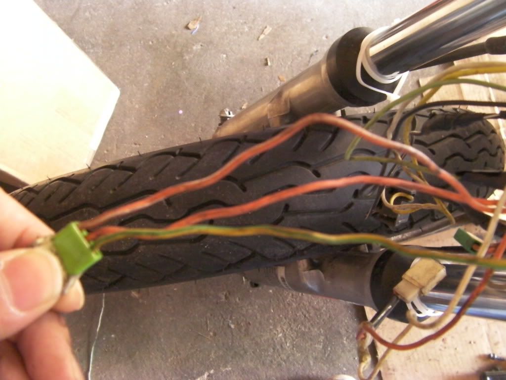
    I know 86 says it should get wires from the switch but i am confused, There are 3 wires comming from the right handlebar switch.. 2 orange and one Green :


    Im Guessing i should solder the two orange wires together put a female connector and hook it up too 86? the green wire goes to wherever it used to go? or do i solder all three?

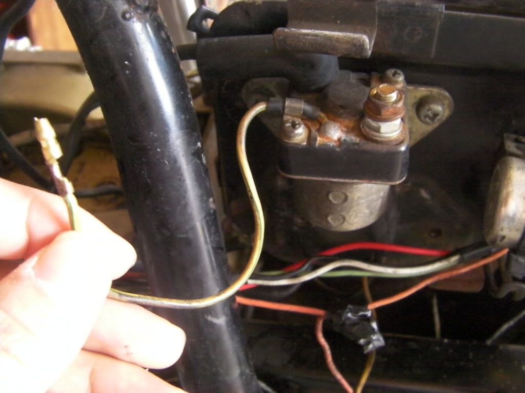
    Also guys i am stuck here with the solenoid.... shouldnt one of these wires goto the relay?


    I am confused at where the wire in my hand goes to... and do i need to route a power wire from the nut to the + battery like there used to be?

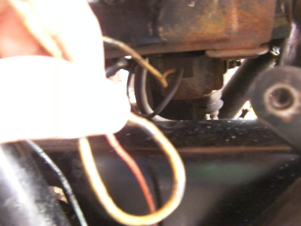
    also guys i know this may seem a bit much but i dont know where this wire goes to, It comes out of the metal heat sink thing mounted on the bottom of the battery bracket..


    thanks guys... i really want to tackle this today but i am just stuck..
    John 3:16

    #2
    If you're following Basscliffs instructions #86 should be your direct positive with an inline fuse (I connected mine to the solenoid instead of the battery, less clutter around the battery post). Your #30 is for the switched relay. You can take this from anywhere that supplies switched power. I tapped into that right at the three wire connector you show in your picture. Can't remember exactly which wire it was (pretty sure it's the green/yellow but don't quote me) but it's simple to figure out, just use a 12V light tester, hit your starter switch and poke around until you find which wire is bringing current back. #85 is the ground as you have detailed as well (make it a good ground). #87 is the coils as you described as well. Now about your solenoid that wire you show connect to your harness, just have a look at your harness for the same color wire and plug them together. On my 79 850 the connector is tucked into a a harness cover (not sure if that's what they are called but it's just a rubber protector thing that goes over the harness where a bunch of connectors are to protect them from the elements, blah,blah,blah). And yes you need to have positive to that connector on the solenoid, and like I mentioned before that's where I connected my direct positive source for the coil relay mod. Now for the "metal heat sink" thing under you battery I think you're referring to your regulator/rectifier. There should be a few wires coming out from that (I can't tell from your pic which wire you have) and they all get plug into another connector and a ground. A couple go to your generator and the other to your ignition switch. The connectors should be around the frame under your left cover, but that depends on what has been done to your harness. You need to look at your wiring diagram and it will all make sense, its fairly simple. There's one on Cliffs site that will work for you or the 79 850 one will work for you as well. Keep us posted. All this info came from my experience with my 79 850 but I'm pretty sure both bikes are very similar in this situation.
    Last edited by azr; 01-10-2011, 05:44 PM.
    Rob
    1983 1100ES, 98' ST1100, 02' DR-Z400E and a few other 'bits and pieces'
    Are you on the GSR Google Earth Map yet? http://www.thegsresources.com/_forum...d.php?t=170533

    Comment


      #3
      Thanks man, Test light it is!! and also there is two regulator rectifiers? i have one aftermarket electrosport that was taken out to be re-wired better i was suprised to see a second thing under the battery.. i will keep you posted! ill post some pictures too tm
      John 3:16

      Comment


        #4
        I'd have to look at your specific manual but since your bike is a 78 it might have the regulator and rectifier as separate pieces. In 79 they started to manufacture them as one unit as is on my 79 850. My 78 1000 has a regulator and a rectifier as seperate units. If this is the case with yours disregard my info about the wiring for your regulator/rectifier unit. Basically just follow your wiring diagram and it will make sense.
        Rob
        1983 1100ES, 98' ST1100, 02' DR-Z400E and a few other 'bits and pieces'
        Are you on the GSR Google Earth Map yet? http://www.thegsresources.com/_forum...d.php?t=170533

        Comment


          #5
          Originally posted by azr View Post
          If you're following Basscliffs instructions #86 should be your direct positive with an inline fuse (I connected mine to the solenoid instead of the battery, less clutter around the battery post). Your #30 is for the switched relay. #85 is the ground as you have detailed as well (make it a good ground). #87 is the coils as you described as well.
          Not sure where azr got his numbers.

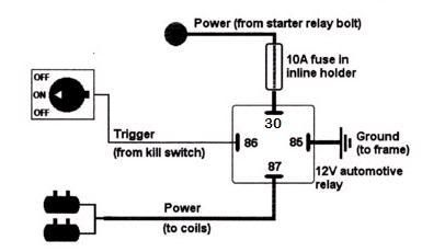
          #30 is the one that is connected to the battery (or the battery side of the starter solenoid) to feed power into the relay.
          #85 can be used as the ground (so can #86)
          #86 can be used as your trigger wire (if you do that, then #85 is your ground)
          #87 is the one that will feed the coils.

          Basically, cut the + wire that feeds both coils at a point where it will meet with the #87 pin of the relay. Connect the wire that got cut to pin #86. Now just hook up your power and ground wires to #30 and #85, respectively, and find someplace to mount the relay.

          This diagram should help:


          .
          sigpic
          mine: 2000 Honda GoldWing GL1500SE and 1980 GS850G'K' "Junior"
          hers: 1982 GS850GL - "Angel" and 1969 Suzuki T250 Scrambler
          #1 son: 1986 Yamaha Venture Royale 1300 and 1982 GS650GL "Rat Bagger"
          #2 son: 1980 GS1000G
          Family Portrait
          Siblings and Spouses
          Mom's first ride
          Want a copy of my valve adjust spreadsheet for your 2-valve per cylinder engine? Send me an e-mail request (not a PM)
          (Click on my username in the upper-left corner for e-mail info.)

          Comment


            #6
            I just took them off of one of cliffs tutorials since that is what GabrielGoes was using but I suppose it's easiest to go by what your own relay says. You've got some good advice here GabrielGoes, should be easy for you now.
            Rob
            1983 1100ES, 98' ST1100, 02' DR-Z400E and a few other 'bits and pieces'
            Are you on the GSR Google Earth Map yet? http://www.thegsresources.com/_forum...d.php?t=170533

            Comment


              #7
              Now for the rest of your questions:
              Originally posted by GabrielGoes View Post
              I know 86 says it should get wires from the switch but i am confused, There are 3 wires comming from the right handlebar switch.. 2 orange and one Green :


              Im Guessing i should solder the two orange wires together put a female connector and hook it up too 86? the green wire goes to wherever it used to go? or do i solder all three?
              Don't do ANYTHING with those wires, they need to get plugged into the socket they came out of. The wire you want for your relay will be found down at the coils.


              Originally posted by GabrielGoes View Post
              Also guys i am stuck here with the solenoid.... shouldnt one of these wires goto the relay?


              I am confused at where the wire in my hand goes to... and do i need to route a power wire from the nut to the + battery like there used to be?
              No. The one in your hand needs to get plugged back into the harness where it came from. That is the wire that comes from the starter button, through the clutch switch to activate the starter solenoid.

              It appears that there is a wire missing from that large terminal on the solenoid. You should have a large (8- or 6-gauge wire) to the battery. That is also where you would connect a 14-gauge wire to #30 on the relay.


              Originally posted by GabrielGoes View Post

              also guys i know this may seem a bit much but i dont know where this wire goes to, It comes out of the metal heat sink thing mounted on the bottom of the battery bracket..


              thanks guys... i really want to tackle this today but i am just stuck..
              Not sure about your 750, but the R/R on my 850s is mounted under the battery box. As azr mentioned, though, your '78 is likely to have separate rectifier and regulator, unless someone has already done an upgrade. Follow the wire down, see what else is there. You might be able to remove the device entirely if it is no longer in use. Easiest way is to remove the stuff that is hanging on the sides of the battery box, remove the battery, unbolt the box and lift it out, then remove the device.

              .
              sigpic
              mine: 2000 Honda GoldWing GL1500SE and 1980 GS850G'K' "Junior"
              hers: 1982 GS850GL - "Angel" and 1969 Suzuki T250 Scrambler
              #1 son: 1986 Yamaha Venture Royale 1300 and 1982 GS650GL "Rat Bagger"
              #2 son: 1980 GS1000G
              Family Portrait
              Siblings and Spouses
              Mom's first ride
              Want a copy of my valve adjust spreadsheet for your 2-valve per cylinder engine? Send me an e-mail request (not a PM)
              (Click on my username in the upper-left corner for e-mail info.)

              Comment


                #8
                Originally posted by Steve View Post
                Now for the rest of your questions:


                Don't do ANYTHING with those wires, they need to get plugged into the socket they came out of. The wire you want for your relay will be found down at the coils.
                I know it needs to be plugged back in the socket but i was reffering (sorry i didnt specify) to the ends of those wires.. i believe the green one is the switch wire that goes back to the loose wire in the next picture (not shown here) but the two orange wires ARE found as loose ends as well down at the coils as you say, im gonna say that those are the wires reffered to as the "kill switch" wires? ... should i solder these together and then throw them on the relay? or is there supposed to only be one wire that should goto the relay?

                also i have a 5 wire electrosport R/R 3 to the stator wires and 1 ground and 1 power.. im guessing i dont need that other thing down there.. im gonna go check it out..

                Thanks for the help Steve and AZR and for everyone that read this thread..
                Last edited by GabrielGoes; 01-11-2011, 01:53 AM.
                John 3:16

                Comment


                  #9
                  im pretty sure i got it down im gonna do this up tommorow asap, im re-reading all posts you guys made it pretty clear, the thing is the P.O. is a total moron who sorta changed everything and it is just overall a mess down there, thank you guys for clearing this up for me i now have a much better idea of what im doing now
                  John 3:16

                  Comment


                    #10
                    Originally posted by GabrielGoes View Post
                    i believe the green one is the switch wire that goes back to the loose wire in the next picture (not shown here)...
                    Correct, that is your solenoid trigger wire.


                    Originally posted by GabrielGoes View Post
                    ... but the two orange wires ARE found as loose ends as well down at the coils as you say, im gonna say that those are the wires reffered to as the "kill switch" wires? ... should i solder these together and then throw them on the relay? or is there supposed to only be one wire that should goto the relay?
                    One of those wires is the feed from the ignition fuse, the other currently goes to the coils and ignitor. You will use the one that goes to the coils and ignitor to trigger your relay (#86). Unfortunately, they are the same color, so you will have to use a meter to see which is which.

                    Was that plug in the picture on the main harness side or the switch side?
                    Knowing that will help me tell you how to test which wire is which.

                    .

                    .
                    sigpic
                    mine: 2000 Honda GoldWing GL1500SE and 1980 GS850G'K' "Junior"
                    hers: 1982 GS850GL - "Angel" and 1969 Suzuki T250 Scrambler
                    #1 son: 1986 Yamaha Venture Royale 1300 and 1982 GS650GL "Rat Bagger"
                    #2 son: 1980 GS1000G
                    Family Portrait
                    Siblings and Spouses
                    Mom's first ride
                    Want a copy of my valve adjust spreadsheet for your 2-valve per cylinder engine? Send me an e-mail request (not a PM)
                    (Click on my username in the upper-left corner for e-mail info.)

                    Comment


                      #11
                      Originally posted by Steve View Post
                      One of those wires is the feed from the ignition fuse, the other currently goes to the coils and ignitor. You will use the one that goes to the coils and ignitor to trigger your relay (#86). Unfortunately, they are the same color, so you will have to use a meter to see which is which.

                      Was that plug in the picture on the main harness side or the switch side?
                      Knowing that will help me tell you how to test which wire is which.
                      .
                      What Plug are you talking about? im not understanding the question fully. the green thing in my hand plugs into the right handle bar killswitch/starter,.. I have a test light with me handy i just borrowed from a friend.. how would i go about finding which one goes to the ignitor and coils? or maybe i can answer your question better somehow
                      John 3:16

                      Comment


                        #12
                        Gabriel, that "green thing", or plug/connector, does plug into the right handle switch assembly but should be connected to another end within the headlight bucket. That's what he is asking about - is it the male end that goes to the assembly or the female end that is on the wiring harness inside the bucket?
                        Cowboy Up or Quit. - Run Free Lou and Rest in Peace

                        1981 GS550T - My First
                        1981 GS550L - My Eldest Daughter's - Now Sold
                        2007 GSF1250SA Bandit - My touring bike

                        Sit tall in the saddle Hold your head up high
                        Keep your eyes fixed where the trail meets the sky and live like you ain't afraid to die
                        and don't be scared, just enjoy your ride - Chris Ledoux, "The Ride"

                        Comment


                          #13
                          GabrielGoes...do you have a wiring diagram for you bike yet?
                          Rob
                          1983 1100ES, 98' ST1100, 02' DR-Z400E and a few other 'bits and pieces'
                          Are you on the GSR Google Earth Map yet? http://www.thegsresources.com/_forum...d.php?t=170533

                          Comment


                            #14
                            i followed the diagrams perfectly, everything works except the bike will not shut off unless i disconnect the battery... the only the the killswitch does on the off position does is prevent the bike from started, when in the on position it allows the bike to be started but i cant find a way to turn the bike off... any ideas?
                            Last edited by GabrielGoes; 01-16-2011, 03:16 PM.
                            John 3:16

                            Comment


                              #15
                              disaster strikes again!
                              John 3:16

                              Comment

                              Working...
                              X