 !!!
!!!
Announcement
Collapse
No announcement yet.
On side of the road right now - bike's not starting
Collapse
X
-
 elrico
Yes ,good idea ..confirm charging system status,all new ,repaired,etc. looking good and then ..maybe something changed,peace of mind checkup always worth the look,best results to you. !!!
!!!
-
 LoopGaroo
Here's what I found out tonight: I don't know jack-sheet about testing circuits.
I thought I found the problem when I inspected the wires inside the kill switch and found a dodgey PO wire splice. I assumed that was the problem and clipped and joined the Orange/white wires together to essentially bypass the kill switch. This gave no result.
After that I pulled the headlight bucket and removed the tank to trace the wires from the switch through the harness to see it I could find any loose wires. No results. everything looked good.
I went ahead and bypassed the clutch safety switch just for peace of mind. I'll probably switch that back when I get this all sorted out.
My biggest problem is my ignorance. I want to be able to try out everyone's suggestions but I'm afraid of doing something wrong and making things worse...I don't fully understand how to follow through on everyone's advice. For example, When tom203 writes: After ignition switch, power is fed back to fuse panel, then to ignition fuse, then back up to kill switch, might be wiring, so just bypass it all with a jumper wire. I don't understand exactly how to bypass everything. Posplayr's advice seemed great too, but again, I don't know exactly where to put the alligator clips to bypass things.
And - even if i didn't hot wire the bike - where does that leave me? What would be broken?
Sorry for my sour tone here, I'm really down about this. My best friend is flying in to town and we're supposed to head out on a motorcycle trip this weekend. things aren't looking too good.
Last edited by Guest; 05-01-2012, 11:31 PM.
Comment
-
 LoopGaroo
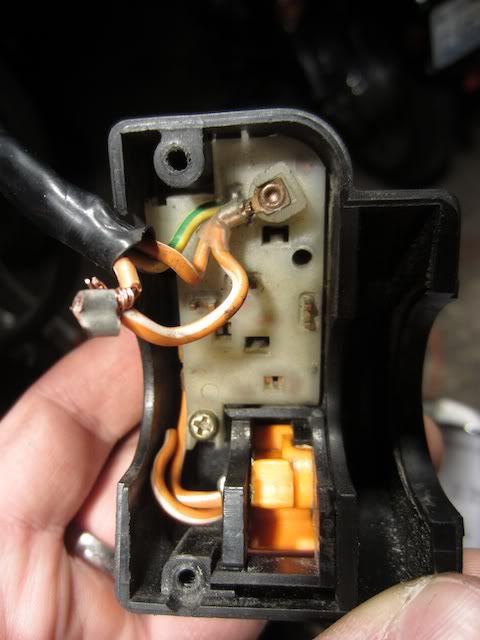
Ok, here's how the switch looks at the moment with the kill switch bypassed:
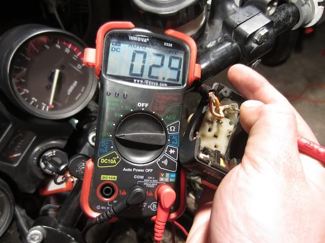
Here I am holding the START button with the negitive lead on the (-) of the battery:
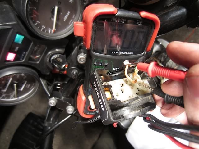
Hehe, I'm not sure what this is showing:
When I was doing this measurement the numbers were just going bonkers: (negative lead is grounded)
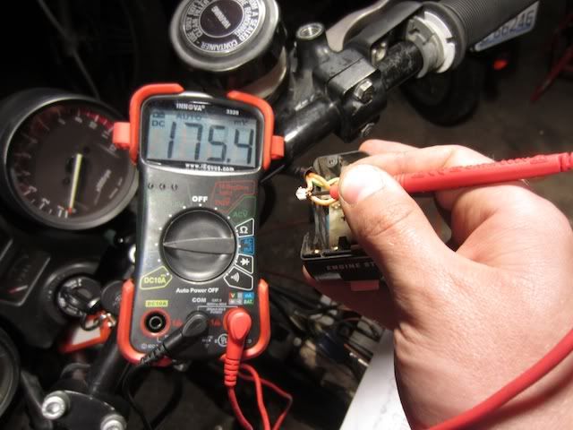
What does it all mean? it's certainly not the 12v that a healthy system would show.
Comment
-
move the meter to 2'Oclock. on "DCV". You are doing a battery load test with the current setting.
 Equus Innova 3320 auto-ranging digital multimeter - technical specifications and operating instructions.
<H4>AC/DC Voltage measurement</H4>
To avoid possible electric shock, instrument or equipment damage, do not attempt to measure voltages above 600V AC/DC. This is the maximum voltage that this instrument is designed to measure. The "COM" terminal potential should not exceed 300V AC/DC measured to ground.
1. Plug the black test lead into "COM" jack of the multimeter then plug the red test lead into the "V" jack.
2. Set the multimeter's Function/Range Selector switch to the appropriate ACV or DCV position as desired .
3. Place the red test lead onto the positive (+) side of the item being tested and the black test lead onto the negative (-) (across the source/load) side of the item. Be careful not to touch any energized conductors with any part of your body.
4. Read the results on the display.
test it first on the battery to see if it is the settings are any good.Last edited by posplayr; 05-02-2012, 01:01 AM.
Comment
-
 elrico
Re-check battery terminals/cables for proper tightness.You did all that charging system component/parts work..loose cable will/can result in symptoms as the bike shows,I only mention this as it has happened to my GS and buzzy Bandit 600 in past..installed extra ground terminals on - post,taking battery in and out,motor buzz/vibes loosening up battery cables little by little etc.Re-check will take little time.Keep battery charged up w/tender for good testing along the way while troubleshooting.
Comment
-
 LoopGaroo
So I got back to the garage this morning and started to figure some things out. Thanks for all the help so far!
- There is not 12v coming into the kill switch on the orange/white wire.
- When I bypass the harness and connect an alligator clip from the battery to the o/w wire in the switch the Start button will crank the bike, with confirmed spark.
- 12v will run through the kill switch to the start button when the button is depressed and the bypass is in place.
- I can also create a bypass from the ignition fuse in the fuse box to the switch and it'll fire.
- I tested a o/w wire where ever I could find one. Under the tank there is a bunch of wires that join in a big plastic connector. There are two o/w wires in this bundle and only one tested as carrying 12v. When I test the other wire the numbers go haywire on the multimeter. (does this mean that there is no current?)
- Also, to the right of the fuse box there was another plastic multi-connector with a o/w with the same crazy readings
I was pretty excited to hear her fire up when I hit the Start button. There is hope! I went by Radio Shack and got a bunch of supplies to sort this thing out.
Comment
-
Great you are finally making progress; you need to just focus on where you have a break in continity between the ignition fuse and the kill switch. It could be an open (bad connection) or a short.
several ways to go about it. I woudl probably start by disconnecting the battery and doing a continuity test.
It is possible you are looking at some harness damage, cut wires, bad contacts so do some resistance checks before upsetting the harness. It might help you identify where any possibel damage is at.
Test #1 - ohm meter between Ignition fuse and ground ==> make sure the circuit is not grounded (should be open from ground)
Test #2 - Ohm meter between Ignition Fuse and the inline connector ==> figure out which wire is coming from the fuse box
Test #3 - Ohm meter between connector pin connected to ignition fuse and ground ==> figure out if the wire feeding the Kill switch is grounded
Test #4 - ohm meter between the mating connector pin (from step 2,3) and the Kill switch ==> see if there is continuity to the Kill switch
Test #5 - ohm meter between the mating connector pin and ground ==> see if the other side of the conenctor is grounded.
basically you are going to confirm that teh path has continuity and that the path is not grounded. Work your way through.Last edited by posplayr; 05-02-2012, 01:01 PM.
Comment
-
There is a plug under the fuel tank. Check that one. It has the O/W wire running through it.
If that is not it I'd suspect the fuse block.1983 GS 1100E w/ 1230 kit, .340 lift Web Cams, Ape heavy duty valve springs, 83 1100 head with 1.5mm oversized SS intake valves, 1150 crank, Vance and Hines 1150 SuperHub, Star Racing high volume oil pump gears, 36mm carebs Dynojet stage 3 jet kit, Posplayr's SSPB, Progressive rear shocks and fork springs, Dyna 2000, Dynatek green coils and Vance & Hines 4-1 exhaust.
1985 GS1150ES stock with 85 Red E bodywork.

Comment
-
 LoopGaroo
If i need to replace a wire, is it possible to remove wire-ends from the connector without cutting?
Comment
-
Forum LongTimerBard Award Winner
GSResource Superstar
Past Site Supporter- Jul 2005
- 15153
- Marysville, Michigan
Yes. There is a tab on most electrical terminals that, when depressed, allows for the terminal to be removed from the hard shell.
I use a small flattened cotter key or a pin to depress the tab.
Comment
-
 LoopGaroo
Okay - got'r started tonight with Posplayr's guidance.
Seems that a wire snapped between the kill switch and the first connection. I'm not exactly sure what caused the break, but the wire was clean-cut. Strange stuff mang...
So I bypassed the wire. It looks kinda funny, and it ain't pretty. My kill switch is bypassed, but it'll hold for the trip this weekend. I can clean up my janky wiring after I get back.
Comment
-
If possible take a picture to see what happened to cause the damage. generally the wiring should be secure so that it doesn't bounce around. Copper is not steel with an infinite life on flex cycles. Copper will eventually work harden and break under vibrations.Originally posted by LoopGaroo View PostOkay - got'r started tonight with Posplayr's guidance.
Seems that a wire snapped between the kill switch and the first connection. I'm not exactly sure what caused the break, but the wire was clean-cut. Strange stuff mang...
So I bypassed the wire. It looks kinda funny, and it ain't pretty. My kill switch is bypassed, but it'll hold for the trip this weekend. I can clean up my janky wiring after I get back.
If there is no other damage then maybe it just got cut so look for what might have done that. Reconnecting (solder or crimp) would get you back to a functional kill switch.
I did see what looked like someones handy work after a broken connection in the attached picture.Last edited by posplayr; 05-03-2012, 10:00 AM.
Comment
-
posplayr is the man!Originally posted by LoopGaroo View PostOkay - got'r started tonight with Posplayr's guidance.
Seems that a wire snapped between the kill switch and the first connection. I'm not exactly sure what caused the break, but the wire was clean-cut. Strange stuff mang...
So I bypassed the wire. It looks kinda funny, and it ain't pretty. My kill switch is bypassed, but it'll hold for the trip this weekend. I can clean up my janky wiring after I get back.1983 GS 1100E w/ 1230 kit, .340 lift Web Cams, Ape heavy duty valve springs, 83 1100 head with 1.5mm oversized SS intake valves, 1150 crank, Vance and Hines 1150 SuperHub, Star Racing high volume oil pump gears, 36mm carebs Dynojet stage 3 jet kit, Posplayr's SSPB, Progressive rear shocks and fork springs, Dyna 2000, Dynatek green coils and Vance & Hines 4-1 exhaust.
1985 GS1150ES stock with 85 Red E bodywork.

Comment
.png)
Comment