Announcement

Collapse
No announcement yet.

Unpotting a TSCU

Collapse
X
 
  • Filter
  • Time
  • Show
Clear All
new posts

    #16
    Originally posted by rustybronco View Post
    No I haven't. It's just conjecture at this point.

    I have 7 or 8 of these units in varying states of function. I guess I could build up a little test platform and see if I can replicate the cause and also it check to see if cooling a particular relay (component?) might cause it to start flashing again.

    I'm deducing it 'could' be one of the problems with these as the relays are exposed to the atmosphere and they tend to corrode and the fact some unit's will stop operating on just one side.
    I was just thinking that if it was primarily the relays, that were failing, something small could be inserted to replicate the relay function with a FET or two.

    That would keep all of the form and function the same.

    We can keep playing 29 questions, which a picture would help.........

    Are the entry wires/solder balls exposed inside of the device? How much room is inside?

    Comment


      #17
      Originally posted by posplayr View Post
      I was just thinking that if it was primarily the relays, that were failing, something small could be inserted to replicate the relay function with a FET or two.

      That would keep all of the form and function the same.

      We can keep playing 29 questions, which a picture would help.........

      Are the entry wires/solder balls exposed inside of the device? How much room is inside?
      28 questions left... http://www.thegsresources.com/_forum...65&postcount=1

      The ends opposite the hard shells are potted along with the rest of the electrical components. The undersides of the two relays (PCB side) are partially obscured making it difficult to replace or unsolder them.
      De-stinking Penelope http://thegsresources.com/_forum/sho...d.php?t=179245

      http://www.thegsresources.com/_forum...35#post1625535

      Comment


        #18
        Originally posted by rustybronco View Post
        28 questions left... http://www.thegsresources.com/_forum...65&postcount=1

        The ends opposite the hard shells are potted along with the rest of the electrical components. The undersides of the two relays (PCB side) are partially obscured making it difficult to replace or un solder them.
        Well the only obvious solution to that is to make a small universal board, cut the wires from the TSCU, solder them to the new board and stuff the whole thing into the original enclosure (or NOT). Then you have the same harness end connections.

        You could repot the thing even with what ever space you can hog out of what is there.

        Comment


          #19
          Originally posted by posplayr View Post
          Well the only obvious solution to that is to make a small universal board, cut the wires from the TSCU, solder them to the new board and stuff the whole thing into the original enclosure (or NOT). Then you have the same harness end connections.

          You could repot the thing even with what ever space you can hog out of what is there.
          Yep, hog it insides out of the old unit to fit a replacement board or mold a new housing. Or, if the replacement unit is small enough, hog out a little of the real estate and fit the replacement under the metal cover.

          In days past, had given thought to making a mold and casting a dozen or so. We'll see what the future holds for me. I might revisit it some day. Need to concentrate on getting the Skunk finished and rebuilding the lean-to attached on the back of my garage this year; plus the house needs to be repainted as well.
          De-stinking Penelope http://thegsresources.com/_forum/sho...d.php?t=179245

          http://www.thegsresources.com/_forum...35#post1625535

          Comment


            #20
            Originally posted by rustybronco View Post
            Yep, hog it insides out of the old unit to fit a replacement board or mold a new housing. Or, if the replacement unit is small enough, hog out a little of the real estate and fit the replacement under the metal cover.

            In days past, had given thought to making a mold and casting a dozen or so. We'll see what the future holds for me. I might revisit it some day. Need to concentrate on getting the Skunk finished and rebuilding the lean-to attached on the back of my garage this year; plus the house needs to be repainted as well.
            I don't see any need to create a mold when the only point of the enclosure is to look like the original and the original is what you already have.

            I'll see if it fits into my schedule.

            Comment


              #21
              Jim, I'll take a picture of thread TSCU later on tonight.

              And they are still available new from Suzuki
              De-stinking Penelope http://thegsresources.com/_forum/sho...d.php?t=179245

              http://www.thegsresources.com/_forum...35#post1625535

              Comment


                #22
                Originally posted by posplayr View Post
                Which part exactly is this? Do you have a picture? How many pins?
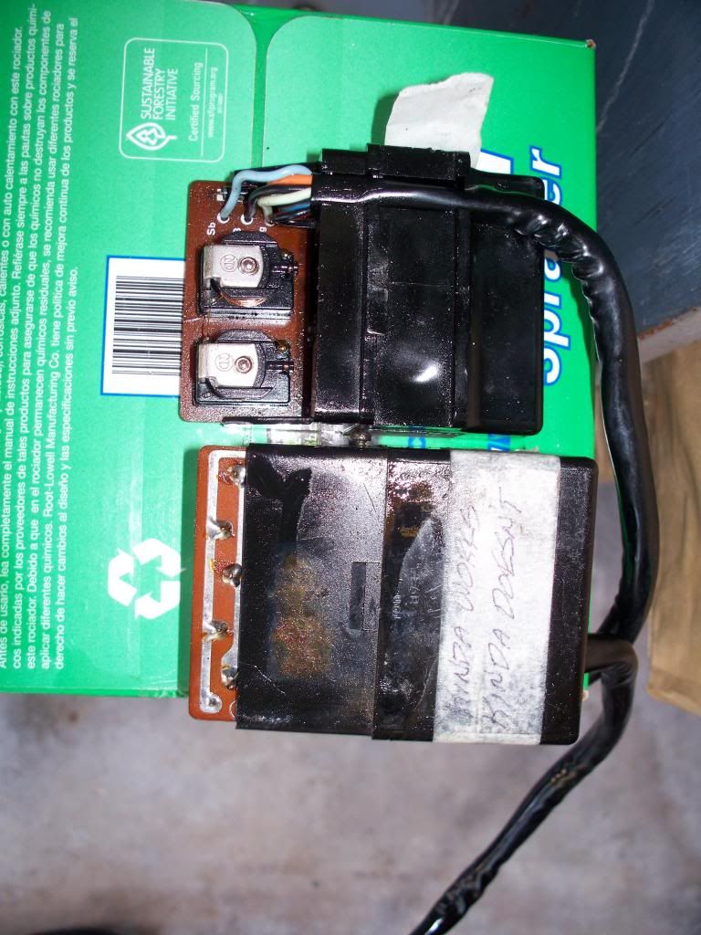
                It's called a 1st Generation Turn Signal Control Unit (TSCU) two leads, two plugs, a 6 & 4 pin I do believe.
                The picture here shows one with the cover removed exposing the circuit card and the colored epoxy used as potting starts just on the other side,
                just below the area you can't see. I just read my note on the tape and started laughing, if you can read it good, otherwise it says "Kinda Works, Kinda Doesn't" and so it is the case with these damn things. Dale, you should be getting that Kinda, Sorta, Definite Maybe working TSCU in the mail soon.
                sigpic
                Steve
                "The world is a book, and those who do not travel read only one page." :cool:
                _________________
                '79 GS1000EN
                '82 GS1100EZ

                Comment


                  #23
                  Originally posted by rustybronco View Post
                  Jim, It it the Turn Signal Control Unit.

                  Here is a flock of them...


                  Operation...

                  The left hand control (turn signal switch) consists of three momentary contact switches. One for left and one for the right turn and the third for manual cancel.

                  Pushing the turn indicator lever to either the left or right, latches the TSCU in it's respective turn mode which allows the current to flow out of the turn signal flasher (a simple bi-metallic flasher) through the the left or right TSCU's internal relays. The flashing (self cancel) will shut off the flashing when one of two conditions are met. The first is when the vehicles speed is above XX miles per hour, as sensed by the reed switch in the speedometer, AND XX seconds have passed. The second is when the operator manually cancels the unit by pushing the turn switch downward.

                  Pins...
                  I'll have to count them when I get home tonight.

                  Ah shucks, I just taped and addressed to you Dale the "flock of them" as the same in the picture, with the exception of one I gave Chuck and the "serviceable" one I already sent to you. I could've, should've counted the pins in each plug.
                  sigpic
                  Steve
                  "The world is a book, and those who do not travel read only one page." :cool:
                  _________________
                  '79 GS1000EN
                  '82 GS1100EZ

                  Comment

                  Working...
                  X