.png "Powered by vBulletin")
My Tach doesn't register anything. I recently had a power surge that blew out all of my lightbulbs, ignitor, and the regulator rectifier was also found to be bad afterward although it was most likely the cause. I can't find parts for this motorcycle tach anywhere, so have been forced to take matters into my own hands.
With the bike ON but not running, I get 12V+ to the orange wire. I get no voltage across the white and orange wires.
With the bike ON and Running, I get a voltage across the orange and white wires that increases with RPM. The meter was set to the 20V scale, the meter determines AC or DC voltage.
I connected a AA 1.5V battery to the tach needle and it jumped to 4000 RPM's.
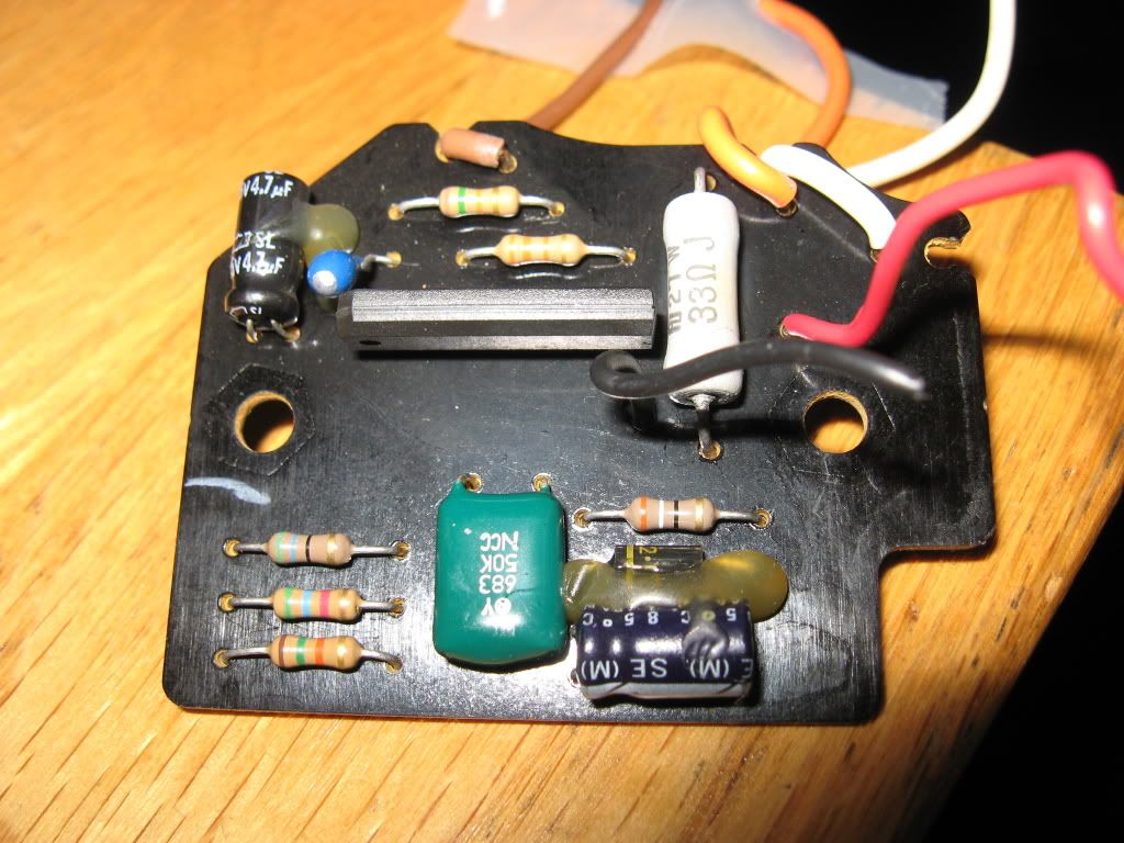
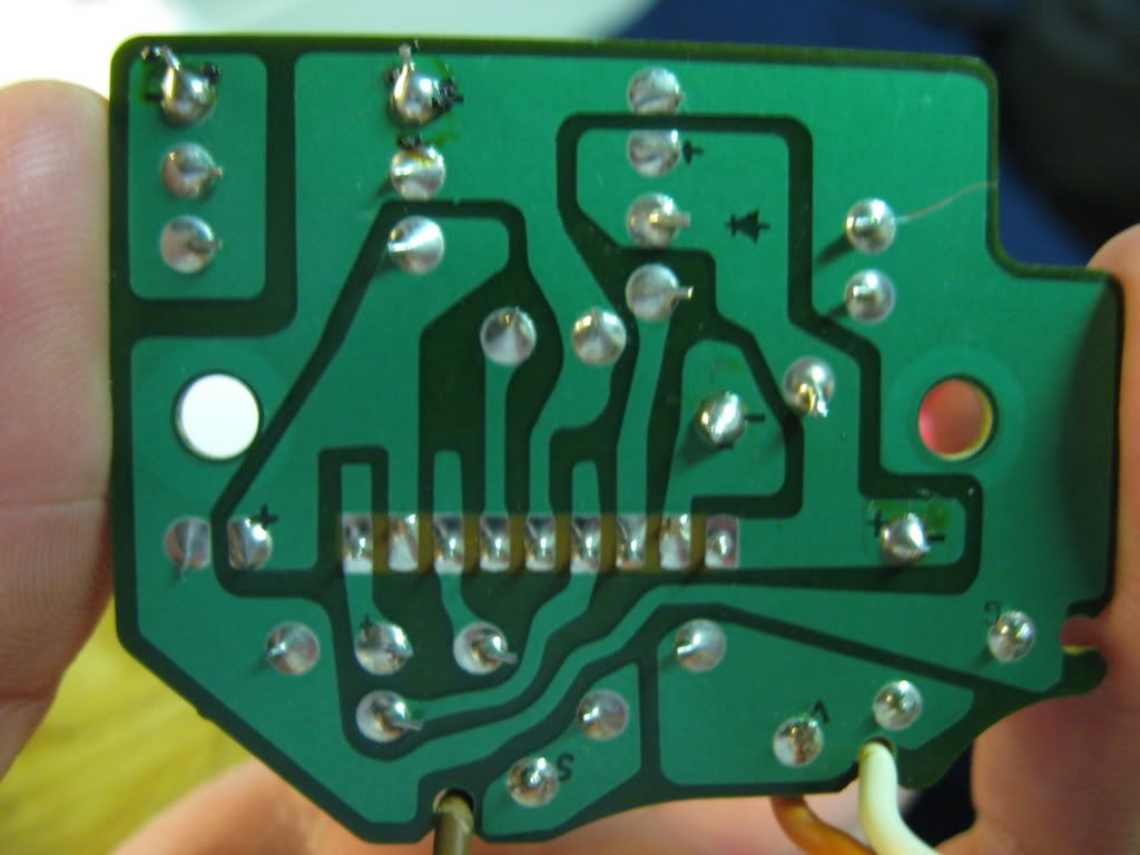
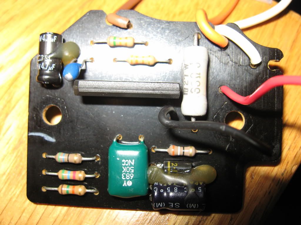
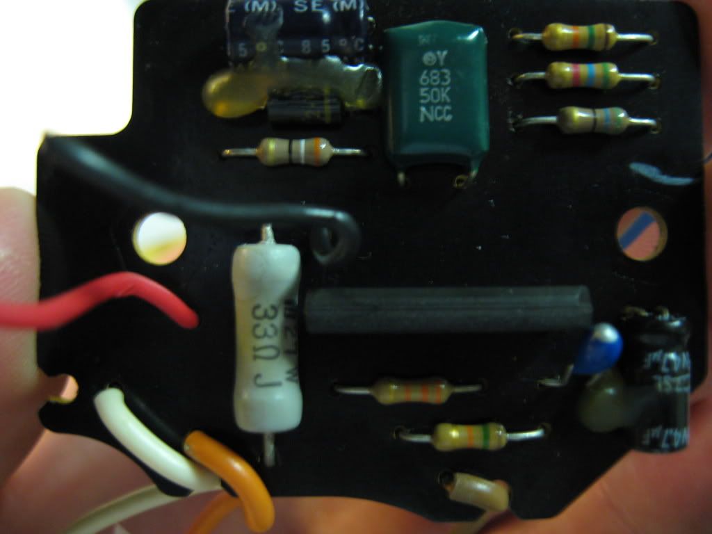
I have concluded that the problem lies in the circuit board between these sets of wires.
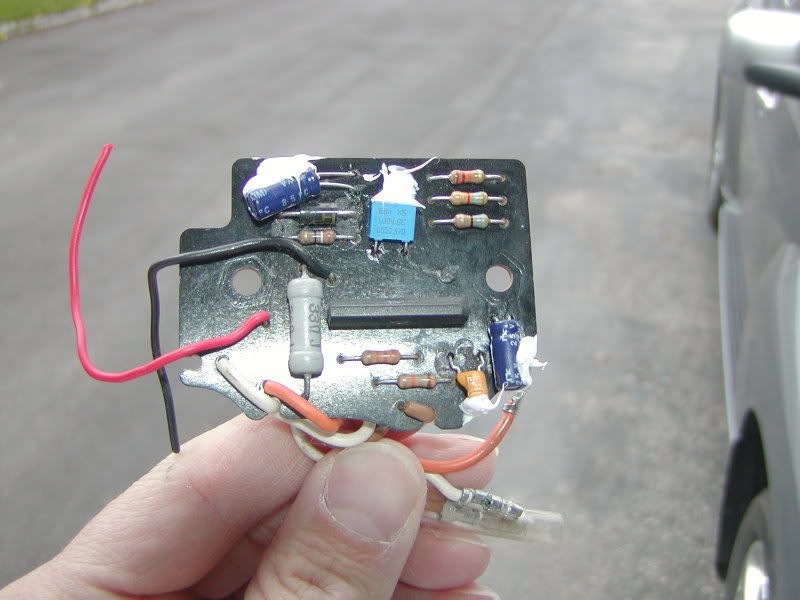
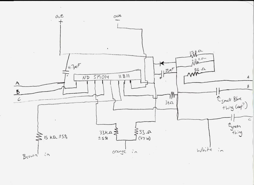
There is no visible damage to the board or the components on the board, although I did measure the resistance across the diode and found it to be .4 ohms, I then reversed the leads to find the same resistance measurement. I did not remove the diode from the board for testing. Does this mean the Diode could be bad?
The black chip in the middle has the letters ND SM014 11B11 stamped on it. If that is the culprit am I screwed? I tried googling that number but didn't find anything.
Please help me, I am trying to get the bike ready for a bike show at Road America in June.
Thanks
With the bike ON but not running, I get 12V+ to the orange wire. I get no voltage across the white and orange wires.
With the bike ON and Running, I get a voltage across the orange and white wires that increases with RPM. The meter was set to the 20V scale, the meter determines AC or DC voltage.
I connected a AA 1.5V battery to the tach needle and it jumped to 4000 RPM's.
I have concluded that the problem lies in the circuit board between these sets of wires.
There is no visible damage to the board or the components on the board, although I did measure the resistance across the diode and found it to be .4 ohms, I then reversed the leads to find the same resistance measurement. I did not remove the diode from the board for testing. Does this mean the Diode could be bad?
The black chip in the middle has the letters ND SM014 11B11 stamped on it. If that is the culprit am I screwed? I tried googling that number but didn't find anything.
Please help me, I am trying to get the bike ready for a bike show at Road America in June.
Thanks
 [/IMG]

.png)


Comment