Announcement

Collapse
No announcement yet.

LED Flasher Unit & Auto Cancelling

Collapse
X
 
  • Filter
  • Time
  • Show
Clear All
new posts

    #31
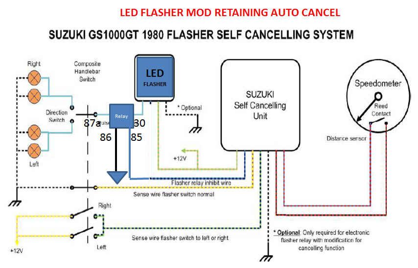
    EDIT: I confirmed the polarity of the 3 plug flasher; C at +12V cancels the flash. I suspect a FET implemented LED flasher will work the same way.

    OK if if the LED flashed will not go open when the ground is lifted then this should work. There are other ways of doing this using FET's but conceptually the same. The current draw on the relay coil is not real significant and once you center your switch the draw will drop to zero anyway.

    I just modified Andre's original diagram from his TSCU repair pdf.


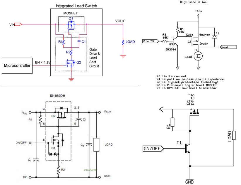
    Looking at 4 different commercial High side switch implementations, each controls a series FET by controlling the Source to gate voltage. This is accomplished by tying a resistor to both the source and gate of the FET and then controlling the current through that resistor. Often providing a switch to ground from the gate does this. This general type of circuit must exist in any LED flasher that uses a high side FET; the control is coming from the timer circuit that causes the flash.

    Since it is the current through the Source to gate resistor that turns the series switch on, blocking that current by lifting the ground will effectively turn off the switch as well. +12V applied to ground should therefore work as the Cancel function in the original OEM relay.

    I'm going to buy something that probably a FET high side switch and hope for the best. The fall back is the external relay as described above.

    Last edited by posplayr; 02-22-2014, 11:32 PM.

    Comment


      #32
      Originally posted by posplayr View Post
      ... but on the OEM flasher:
      • C is for CANCEL ...
      Are you sure it's "Cancel"?

      It might be "Control".

      I looked into the matter briefly (all my signals are still working fine, so there wasn't much incentive) some time ago, and found that if the turn signals are flashing, grounding the "C" wire would stop them. I also tried to get a good reading on the status of the "C" wire (dark blue, I think) while the signals were flashing, but connecting a meter must have been enough of a "ground" to cancel the system. Or, it might have been enough of a drain to remove a very small amount of "high" signal that was turning the flasher unit ON.

      I have come to the conclusion that there must be a small electronic relay built in to the flasher unit that is turned on by the "C" wire (which comes from the control unit) and allows the current to flow from the orange/green wire, through the flasher unit and come out as intermittent current on the light blue wire, which is then fed to the turn signal switch, which determines which side it will go to. Since nothing moves physically to stop the current flow, I think it's inside the flasher unit, which is why you can not get one off the shelf at any parts store to replace it.

      I was hoping to be able to do something like your first diagram, but probably have the relay in the power side of the LED flasher, rather than the load (flashing) side, but was not able to determine whether that signal wire would be able to activate a relay.

      If you are able to come up with a "Solid State Self-Cancelling LED Flasher" box (and keep the cost reasonable), I will get a few from you.

      .
      sigpic
      mine: 2000 Honda GoldWing GL1500SE and 1980 GS850G'K' "Junior"
      hers: 1982 GS850GL - "Angel" and 1969 Suzuki T250 Scrambler
      #1 son: 1986 Yamaha Venture Royale 1300 and 1982 GS650GL "Rat Bagger"
      #2 son: 1980 GS1000G
      Family Portrait
      Siblings and Spouses
      Mom's first ride
      Want a copy of my valve adjust spreadsheet for your 2-valve per cylinder engine? Send me an e-mail request (not a PM)
      (Click on my username in the upper-left corner for e-mail info.)

      Comment


        #33
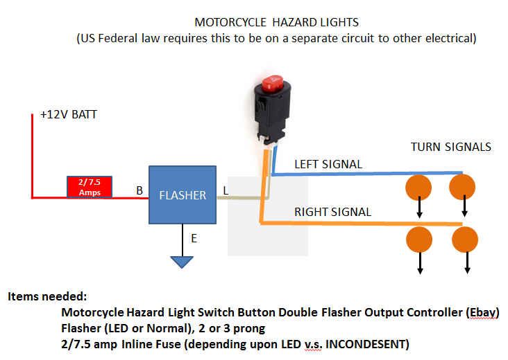
        In reference to the discussion below, this is a pretty easy HAZARD light implementation using a Hazard switch available from multiple vendors on ebay.
        DOT requires that this circuit be independent of the rest of the vehicle electronics. It is about $15-$20 in parts.


        Originally posted by Normk View Post
        Willie, I believe that it is better to express one's impression or feelings regarding a post than to assume as it provides the opportunity for clarification. Clarification usually removes the concern, or at least gets the conflict into the open.

        The shunt simply loads the circuit in the same fashion as do the original incandescent bulbs, such that the flasher is able to function. Other ways to accomplish flashing of light loads such as LEDs which I recall using:
        1) Aftermarket flasher units are made expressly for LED and other light loads.
        2) Connecting the flasher to ground by way of a resistor or diode string to cause the flasher to operate and using a normally closed relay shunted across the flasher. Causes the LEDs to flash in reverse to the flasher but is reliable. The third/indicator terminal of some flashers works well for this purpose.
        3) Use of a flasher bulb to control the relay coil as these are both available in lower voltages which can be combined with a resistor. I used one from a flash light to make the warning light on a boat house flash when the temperature dropped too low.

        Lots of ways to do this. Someone suggested using an electronic timer/flasher from Mouser or one of those suppiers for this purpose on one of the KLR groups. I like to use a simple relay combination although the electronics gurus will often cob together a circuit. Personally, I think they only do it to make we dinosaurs feel even more inferior but if that's the reason, it works.

        On another, related, subject, has anyone bridged the R&L signal light leads in order to achieve 4-way flashers? I always get around to this modification but am a bit concerned about doubling the signal light load into that controller.

        As everyone will know, there are two common means of achieving 4-way flasher operation. The most simple is to connect a switch between the right & left signal bulb leads. Activate the turn signals in either direction and close the switch so that both side turn signals are powered from the side which is activated. Simple and works efficiently. I use it frequently on my ST1100 when moving slowly in traffic as in a construction zone.

        Another means is that which is used by automobile manufacturers who wish to make the 4-ways active when the ignition is off. They often have a much more complex signal switch which allows the brake lights and rear signals to share the same bulb filaments. In even the simpler systems which use separate brake and turn indicators, the 4-way system is powered separately through its own switch and flasher. I don't bother with that system on a bike because, IMO, the battery capacity is insufficient to allow the 4-ways to endure. If one wished to have a 4-way system which could operated for 1/2 hour or longer, sufficient time to repair a tire for example, LED's or HID strobes would need to be considered. I have an LED light bar transversely mounted under the luggage rack on the top of my ST1100's Givi trunk which uses a two wire flat connector to connect to the bike's harness. This allows the LED bar to be connected to the always powered battery charging plug stored behind the rear side cover. The same plug is also power for pillion heated vesta as this will not remain connected to drain the battery.

        An acquaintance connected a relay to flash the opposite side signals but managed to wire it so that the lights alternated side to side. He received official attention almost the first time used, and brought it by for help. I proposed that we simply install one red and one blue lenses onto his front signals but he was not amused.

        I'm not a fan of LED's as turn signals, indicators or brake lights unless their performance is at least equal to incandescent which is seldom the case. The practical issue is that the lighting enclosures and lenses are a problem. There are many excellent purpose designed LED lights on the market but few original lighting units perform well with an LED.
        I think the answer is usually to replace the complete light but that is an issue with a collector bike.

        Comment


          #34
          Originally posted by Steve View Post
          Are you sure it's "Cancel"?

          It might be "Control".

          I looked into the matter briefly (all my signals are still working fine, so there wasn't much incentive) some time ago, and found that if the turn signals are flashing, grounding the "C" wire would stop them. I also tried to get a good reading on the status of the "C" wire (dark blue, I think) while the signals were flashing, but connecting a meter must have been enough of a "ground" to cancel the system. Or, it might have been enough of a drain to remove a very small amount of "high" signal that was turning the flasher unit ON.

          I have come to the conclusion that there must be a small electronic relay built in to the flasher unit that is turned on by the "C" wire (which comes from the control unit) and allows the current to flow from the orange/green wire, through the flasher unit and come out as intermittent current on the light blue wire, which is then fed to the turn signal switch, which determines which side it will go to. Since nothing moves physically to stop the current flow, I think it's inside the flasher unit, which is why you can not get one off the shelf at any parts store to replace it.

          I was hoping to be able to do something like your first diagram, but probably have the relay in the power side of the LED flasher, rather than the load (flashing) side, but was not able to determine whether that signal wire would be able to activate a relay.

          If you are able to come up with a "Solid State Self-Cancelling LED Flasher" box (and keep the cost reasonable), I will get a few from you.

          .
          Yea not really sure if control or cancel; I was reading Andre's write up.

          So as best you can tell the C line needs to be at ground to stop flashing? Well it doesn't matter the relay could be rearranged for that. Put one side of the coil on O/G and let the control box short it.

          You are correct the relay could probably be put on either side. Not really sure which is better other than what the flasher will do when you keep pulling power from it.

          I will have to get my scope out tommorow and measure it. Those at 10M ohm probes I think should be high enough impedance to solve the mystery. Either than or a current clamp.

          At this point I'm after bigger fish but if I do some prototypes and have some PCB space I might knock out a few PCB's to accommodate. If this relay with flasher works it might just be to support that.
          Last edited by posplayr; 02-22-2014, 11:03 PM.

          Comment


            #35
            Originally posted by Steve View Post
            Are you sure it's "Cancel"?


            If you are able to come up with a "Solid State Self-Cancelling LED Flasher" box (and keep the cost reasonable), I will get a few from you.

            .
            I pulled some stuff out of the drawer and put together a prototype; whatta do ya think?
            LED Flasher (automotive or Motorcycle): I replaced the incandescent turn-signal bulbs in my Kawasaki Concours motorcycle with LEDs because 1) they brighter 2) they last longer and 3) they require less current than incandescent bulbs. Because they require less current, the standard flas…

            Comment


              #36
              I did a bench test, on the three prong relay conencted to two turn signal in parallel using a +12V supply. When I leave C open the flasher runs two lights but not one (as expected). When I ground the C terminal is clatters. When I applied +12V to the C terminal the flasher stops in the off position. So +12V means CANCEL.

              When I get my LED flasher I will see if it is plug and play or if the external; relay is required.

              I did not bother to figure out the mechanization, but here is another thread from some guys adding in a FET to short out the capacitor in theirs. It makes sense that if the voltage across a capacitor is what energizes a coil to close the contacts that shorting it would prevent further flashing. Matters not as I'll be using a solid state LED flasher .

              Thanks to some other members' help, i was able to replace my busted and rusted original flasher relay with a new one. Sounds simple enough, but our...
              Last edited by posplayr; 02-23-2014, 12:37 AM.

              Comment


                #37
                Jim, Here is Andre's flasher schematic.
                http://www.mediafire.com/view/ez5i73...1000+1980.docx (open with Open Office)

                Link to the rest of his files. http://www.mediafire.com/?ofnzy51uly4h6
                Last edited by rustybronco; 02-23-2014, 03:00 AM.
                De-stinking Penelope http://thegsresources.com/_forum/sho...d.php?t=179245

                http://www.thegsresources.com/_forum...35#post1625535

                Comment


                  #38
                  Originally posted by rustybronco View Post
                  Jim, Here is Andre's flasher schematic.
                  http://www.mediafire.com/view/ez5i73...1000+1980.docx (open with Open Office)

                  Link to the rest of his files. http://www.mediafire.com/?ofnzy51uly4h6
                  Thanks Dale,

                  I had PMed Andre and he PMed those back as well. I think I basically understand the issues. I'm looking at some other alternatives as I really hate to open up a sealed relay unit.

                  I'm pretty sure that there is a simple solution to modify the harness in one place and then you can mix and match aftermarket relays and OEM turn control units.

                  More later.

                  It is later

                  Last edited by posplayr; 02-23-2014, 08:35 PM.

                  Comment


                    #39
                    Jim,
                    When I played around a while ago I also made up a separate interface unit, but scrapped that idea as another little black box would start complicating matters. Basically the only thing to watch is the output from the cancelling unit. You do not want to damage a part that is hard to get to! It also did not operate a 12V relay so I used a 5V with a series and a parallel protection diode, for reversed connection and back EMF protection.

                    My reasoning for modifying the flasher relay is that the OEM flasher relay is already a custom made one and only works on the 5 position switch type turn signals, so to make an aftermarket drop-in seemed to me a good idea at the time.


                    Just another note the OEM flasher relay works in reverse to others, it is normally on and the lights go off when the relay operates. This allows for the cancelling function by keeping the relay operated through its 2nd 100 ohm holding coil and the lights then stay off while the relay is operated!
                    The switch position when normal does not connect battery to the relay and the lights are then off although the contact in the flasher relay is normally closed.

                    Hope this helps

                    Comment

                    Working...
                    X