S
schmitty78
Guest
In your case you still have to run through the same "T" connection inside of the harness regarless if you run both R/R and Battery through a fuse or not. The R/R doesnt need fusing as it can only produce 15 amps. The battery much more. By fusing the R/R (with the battery) you need a larger fuse (20+ amps v.s. stock 15 amps) which is less protection against a battery short.
In the interest of doing things 'right', and having the most reliability out of my bike, I suppose I will just modify the wiring I have, install a new inline fuse back to the factory spot (with better connections & correct gauge wire), between the battery and the "T". Maybe I'll just see if I can get my money back on the wiring kit for the R/R (+) & (-). If not, would there be anything wrong with using the 14ga wire from Eastern's kit to go to the factory "T"? Other than that, my last 2 challenges are:
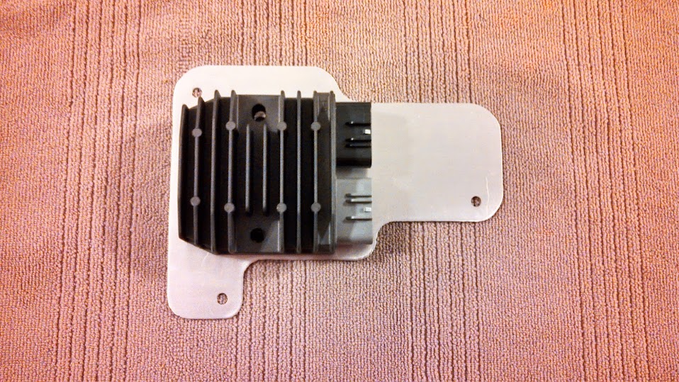
1) making a decent looking mounting plate, so I can re-locate the R/R underneath the right side cover, just above where the battery slides out...seems to be about the only spot it will fit on the 450's without other major modifications.
2) re-working the factory grounding.
Pos (Jim), I know you've received some grief over your ground loops/single point grounding strategy, but from what I've read, I see the theory behind it and agree with it. Do you still use the following strategy, from your thread from a few years back?
1.) Three wires tied together at a mounting bolt for the R/R at the side plate
a.) R/R (-) from the Honda regulator to ring lug on a mounting bolt
b.) Battery (-) to a ring lug on the same mounting bolt
c.) Frame ground strap from bolt to frame (not the rubber mounted side plate)
2.) R/R (+) goes to the fuse box as normal
3.) Only connection other than 1b above to battery (-) is the 8 guage wire ground strap to the engine.
")