T
TPL
Guest
I have a fully functioning stator from my 700 if it works for your bike. If you need one let me know.
Ranger, thanks for the offer
")
Required reading for all forum users!!!
Welcome!
Register to access the full functionality of the GSResources forum. Until you register and activate your account you will not have full forum access, nor will you be able to post or reply to messages.
A note to new registrants...
All new forum registrations must be activated via email before you have full access to the forum.
A Special Note about Email accounts!
DO NOT SIGN UP USING hotmail, outlook, gmx, sbcglobal, att, bellsouth or email.com. They delete our forum signup emails.
A note to old forum members...
I receive numerous requests from people who can no longer log in because their accounts were deleted. As mentioned in the forum FAQ, user accounts are deleted if you haven't logged in for the past 6 months. If you can't log in, then create a new forum account. If you don't get an error message, then check your email account for an activation message. If you get a message stating that the email address is already in use, then your account still exists so follow the instructions in the forum FAQ for resetting your password.
Have you forgotten your password or have a new email address? Then read the forum FAQ for details on how to reset it.
Any email requests for "can't log in anymore" problems or "lost my password" problems will be deleted. Read the forum FAQ and follow the instructions there - that's what we have one for...
If you are a returning visitor who never received your confirmation email, then odds are your email provider is blockinig emails from our server. The only thing that can be done to get around this is you will have to try creating another forum account using an email address from another domain.
If you are a returning visitor to the forum and can't log in using your old forum name and password but used to be able to then chances are your account is deleted. Purges of the databases are done regularly. You will have to create a new forum account and you should be all set.
I have a fully functioning stator from my 700 if it works for your bike. If you need one let me know.
The new stator installed, Extra long wiring a plus, plenty to run directly to the R/R. Bullet connectors will be history.
Nice work!
Nothing wrong with bullets as long as they are the proper size for the wires.
Nice work!
Nothing wrong with bullets as long as they are the proper size for the wires.
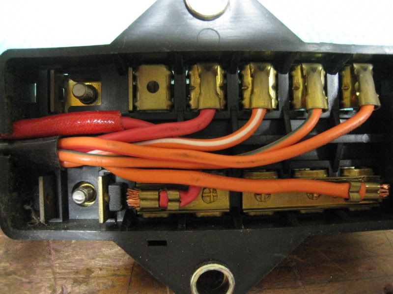
Sorry, one more...I've been told its better to solder the connections inside the fuse box itself. Here's mine opened up and it looks brand new to me. Should I leave it alone since its in this condition?
I got my new stator and R/R today, the R/R, SHINDENGEN FH012AA will be a direct bolt up with no modification, screw holes match. I will be using an inline fuse instead of the original wiring in the bike to the fuse box, the new wire is 10g. The new stator has longer wires than the original with bullet connectors, I will lose the bullet connectors and only have to use the new blade connectors at the new R/R, so no inline connectors will be needed. I'm still waiting on my mag cover gasket but will at least get all the wiring done today.
The schematic shows the original pos to the original R/R was only tied in to the pos ignition line, and the w/g and w/r wires are just a loop for a headlamp switch, none on the 1982. All will be capped with shrink tube.
That is called the "T". Current comes ceom either the R/R(+) or the Battery(+) in alternating pulses (as the R/R switches on and off) to feed the electrical system.
The R/R(+) is not fused because there is only some 15 amps that it can generate and that is at 3-4K RPM. The battery will produce very high currents if shorted (50-100 amp) so it needs to be used into the "T".
When you wire the R/R directly to the battery, current now has to flow to the battery (through your fuse) and then back through the stock fuse block to get to the "T". At that point you are back to the stock current paths.
You should still keep the negative wire to a minimum length at a convenient single point ground.
I'm unfamiliar with the 8V but on a 16V I think you have a problem routing those stator wires with a connector on the end.
For future reference the loop to the head lamp bucket switch is now spare wring that can be used in the future for some other purpose. I use one leg for a coil relay control.
As I said earlier, I had (from the stator to the rr) a white/blue and yellow wire. I also had a white/green out of the rr, which went somewhere in the harness. The white/red out of the stator was also buried in the harness. Finally, I looked at the wiring diagram, and even though white/red went to white/red, and white/green went to white/green in the rubber boot, later upstream, they do connect to each other, and I saw the loop, although the w/g and w/r create the loop. So, in effect, I thought I only had 2 wires feeding the rr from the stator, but it was actually 3.To eliminate feet of wire and lots of crimps, I took the advice here, and connected the w/g from the rr to the w/r out of the stator. No smoke, no fire, no explosions.
Are you saying I will have better, higher charging voltages wiring the new R/R to the T instead of direct to + battery? The info I have on this R/R is to run pos to battery and looking at the schematic I see no reason not to. Perhaps I'm missing something, Maybe I do not understand what you are saying?
Yes, the stator wire blade connectors cannot be clicked in to the connector housing at R/R until they are routed on the bike. But the can always be removed from the connector housing if another stator is ever needed.
Picture shows stator blade connectors to be routed before they are clicked in to the connector housing, then housing plugs to R/R.
I was just clairifying your assessment of how the R/R (+) was connected to the harness.
As far as your harness is concerned, there is functionally no difference between the FET R/R you are planning to use and the OE R/R you took out. Therefore if you choose to rewire your harness as you described you are changing the current paths as I described.
I can't tell you which will have a higher charging voltage as that is a function of how good your various connections are. I think I already described the differences in the two different configurations.
I see now you have individual spades so routing should be OK.
OK, after re reading your post. So running directly to pos battery can cause increased amperage spikes from the battery and take out the 15a stock main fuse.
I've wired the charging system direct to the battery (though a fuse) on some bikes, and into the regular fuse box on others. The bikes wired direct to the battery usually show a higher charging voltage feed into the battery by .5 volts, but I don't know what this is telling me, and which is better. My current bike is wired though the fuse box because I didn't want to mess with an aux fuse and the charging system voltage was showing low until I bought a new battery. The old battery was known to be decent but apparently, not perfect. Again, not sure what this is telling me. Wish there was definitive word on this detail so I could stop guessing.